


![]() Sun Apr 18, 2010 8:12 pm
Sun Apr 18, 2010 8:12 pm
EVVA 3KS
Here is a nice review of the 3KS and how it works:
(this is a direct copy of what is on my website and can be found along with other locks @ http://www.locksmitharmy.com/locks.php)
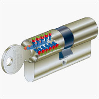
The EVVA 3KS has 3 sidebar like things that interact with the housing. 2 are true sidebars that contact the housing and 6 slider pins each, and the third contacts the top of the key which has a number of angled cuts in it.
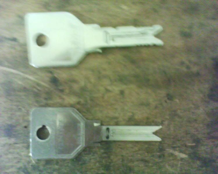
The keys have 3 sidewinder lines cut in each side, each line is a different depth. It also has a V shape cut at the tip. The V cut catches all the sliders and forces them into a chanel where they are slit along the sidewinder cuts based on depth and number of pins, which you will read about next. The keys also interact the sidebard on the side at the enlongated notch just before the bow of the key.
Next, the sliders, contact the key and the sidebars. On one side are round pins that interact with the key, and the other side has notches which interact with the sidebar. You may notice some sliders have 2 pins and others only have one. Now look back at the key. you may notice 2 of the 3 lines are exactly the same, these 2 lines dont go as far into the key as the 3rd line. So the double sliders go in the 2 lines that are alike, and the single sliders dont go in either of those lines because they are to long to fit, so they are pushed all the way to the center of the V cut and enter the 3rd "unique" line.
Now we get to the sidebars themselves. The 2 outer sidebars (on the outside of the image) have 2 springs each and a large tab to the front which goes through the plug and into the key and a small tab which also goes into the plug. The part of these 2 sidebars that contact the pins are the 2 lines that are above and below the springs. These 2 lines sink into the 2 cuts in each slider pin. The 3rd sidebar sits ontop of the key and it has angled cuts that match the angled cuts on top of the key. When picking this is not a bother because if the wrong key is inserted this sidebar will be pushed up into the housing, if NO key is inserted, the sidebar is not pushed up at all, so it is ignored.
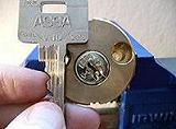
You can see in the plug, at the very top, is the sop sidebar, just to the side of that are 6 holes for 6 slider pins, there are 6 holes on the other side aswell. These 12 holes go all the way through the lock so the slider pins can extrude to the top or bottom of the plug and into the housing, and it will still turn (you will see in the next paragraph). On the median of the plug is a large slot for 1 sidebar, on the other side is the same slot, you can see the spot for the 2 tabs to sink in to keep the sidebar straight, and the front slot goes all the way through so the sidebar can contact the key.
Lastly the housing.The housing has slots for all the sidebars and slots for all the slider pins to extrude. This means, as stated before, that the pins can extrude from the plug and the lock still work, this makes taking the lock apart a pain.
Because I have to many pictures and not enough words, I will explain how to take this lock apart if you have one. On the tailpiece there is a little cover that is held in by a roll pin, this pin needs to be knocked out, I used a 1/16in drill bit and it fit perfectly, hit it with some pliars I had handy and it popped right out(easier than expected). Then the circlip that is on every lock, no big deal. Now to finally remove the plug you need to get all the sliders pulled into the lock, so hitting it on one side should knock the sliders to that side... then slide a shim in the other side. Then knock the lock on the side that the shim is in and it will push all the sliders aginst the shim, and the plug will slide out. The key is not necessary.
Now to the fun part, to pick this lock you need a long thin prod to raise and lower each slider pin, tension is applied normally and the top sidebar is ignored. I have not picked this lock with all its sliders in it, but I am getting there.
(this is a direct copy of what is on my website and can be found along with other locks @ http://www.locksmitharmy.com/locks.php)
The EVVA 3KS has 3 sidebar like things that interact with the housing. 2 are true sidebars that contact the housing and 6 slider pins each, and the third contacts the top of the key which has a number of angled cuts in it.
The keys have 3 sidewinder lines cut in each side, each line is a different depth. It also has a V shape cut at the tip. The V cut catches all the sliders and forces them into a chanel where they are slit along the sidewinder cuts based on depth and number of pins, which you will read about next. The keys also interact the sidebard on the side at the enlongated notch just before the bow of the key.
Next, the sliders, contact the key and the sidebars. On one side are round pins that interact with the key, and the other side has notches which interact with the sidebar. You may notice some sliders have 2 pins and others only have one. Now look back at the key. you may notice 2 of the 3 lines are exactly the same, these 2 lines dont go as far into the key as the 3rd line. So the double sliders go in the 2 lines that are alike, and the single sliders dont go in either of those lines because they are to long to fit, so they are pushed all the way to the center of the V cut and enter the 3rd "unique" line.
Now we get to the sidebars themselves. The 2 outer sidebars (on the outside of the image) have 2 springs each and a large tab to the front which goes through the plug and into the key and a small tab which also goes into the plug. The part of these 2 sidebars that contact the pins are the 2 lines that are above and below the springs. These 2 lines sink into the 2 cuts in each slider pin. The 3rd sidebar sits ontop of the key and it has angled cuts that match the angled cuts on top of the key. When picking this is not a bother because if the wrong key is inserted this sidebar will be pushed up into the housing, if NO key is inserted, the sidebar is not pushed up at all, so it is ignored.
You can see in the plug, at the very top, is the sop sidebar, just to the side of that are 6 holes for 6 slider pins, there are 6 holes on the other side aswell. These 12 holes go all the way through the lock so the slider pins can extrude to the top or bottom of the plug and into the housing, and it will still turn (you will see in the next paragraph). On the median of the plug is a large slot for 1 sidebar, on the other side is the same slot, you can see the spot for the 2 tabs to sink in to keep the sidebar straight, and the front slot goes all the way through so the sidebar can contact the key.
Lastly the housing.The housing has slots for all the sidebars and slots for all the slider pins to extrude. This means, as stated before, that the pins can extrude from the plug and the lock still work, this makes taking the lock apart a pain.
Because I have to many pictures and not enough words, I will explain how to take this lock apart if you have one. On the tailpiece there is a little cover that is held in by a roll pin, this pin needs to be knocked out, I used a 1/16in drill bit and it fit perfectly, hit it with some pliars I had handy and it popped right out(easier than expected). Then the circlip that is on every lock, no big deal. Now to finally remove the plug you need to get all the sliders pulled into the lock, so hitting it on one side should knock the sliders to that side... then slide a shim in the other side. Then knock the lock on the side that the shim is in and it will push all the sliders aginst the shim, and the plug will slide out. The key is not necessary.
Now to the fun part, to pick this lock you need a long thin prod to raise and lower each slider pin, tension is applied normally and the top sidebar is ignored. I have not picked this lock with all its sliders in it, but I am getting there.
You do not have the required permissions to view the files attached to this post.

Pokey wrote:"Come and get me, loser! Spankity spankity spankity!"


