


![]() Wed Apr 06, 2016 3:25 pm
Wed Apr 06, 2016 3:25 pm
Re: LocksportSouth's Stash
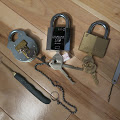
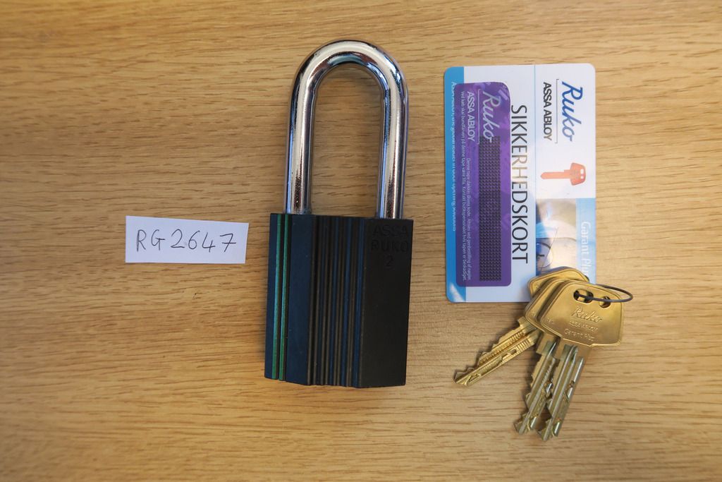
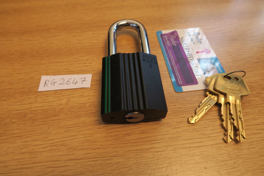
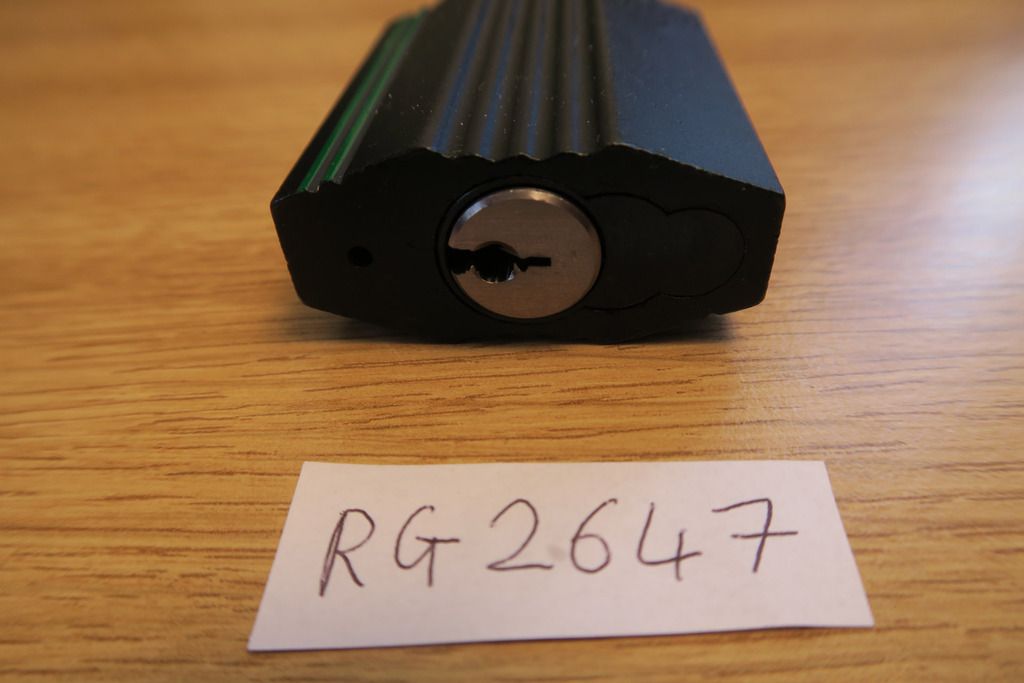
Welcome! With the Ruko RG2647, we’ve officially left the 1200 series / D12 core behind – all locks from here on out use the Garant Plus core, Ruko’s top-tier core which integrates a cool laser track sidebar system. We’re still continuing up through the ranks so we’re still on grade 2 / green stripe locks at the moment – today we’re looking at the 2647.
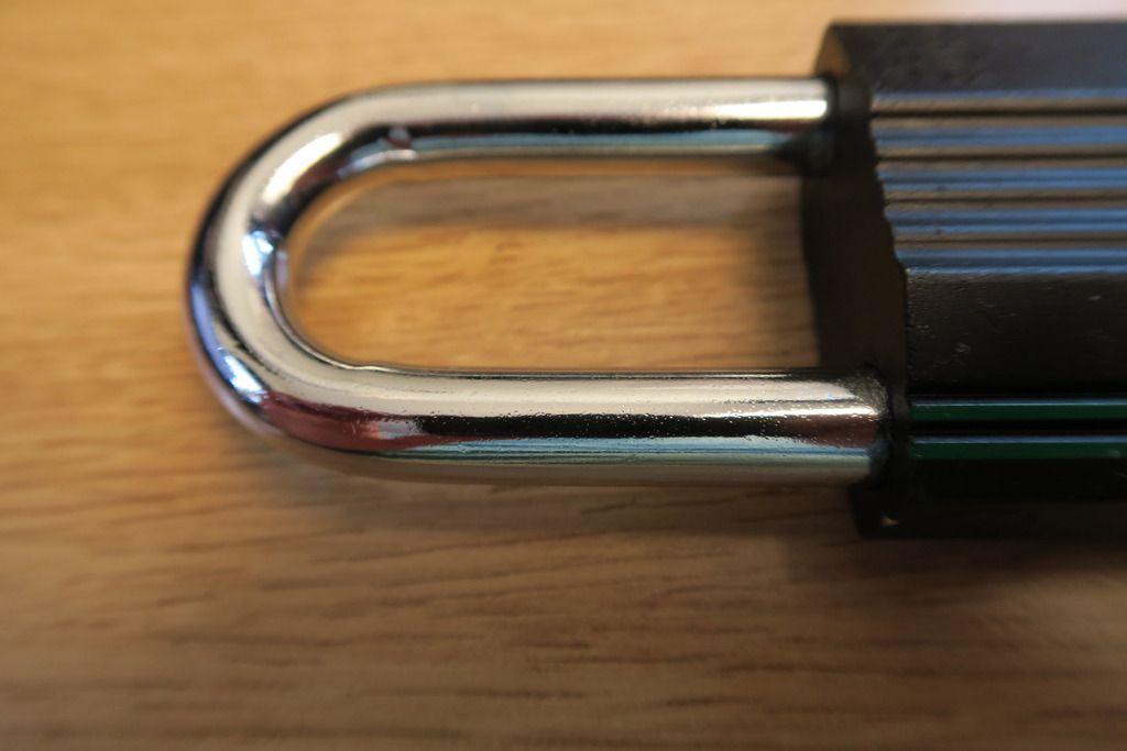
The 2647 takes the shackle length of the 2643 (52mm) and combines it with the shackle thickness of the RG2646 (10mm). Internally, the lock is still the same as the 2641 (and really all other green stripe / grade 2 Rukos, except the shutter lock), however it differs from the 2641 in that the shackle is both longer and thicker. This is the last such identically-bodied grade 2 Ruko padlock that we’ll be looking at.
Of course, this one also has a different core, so we’ll be stripping that down in this post!
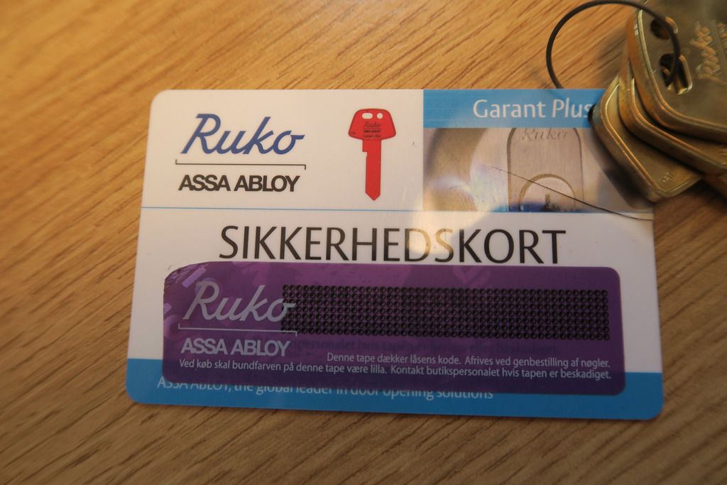
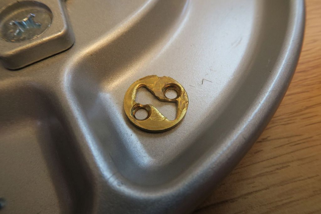
The Garant Plus core also comes with a snazzy credit-card sized code card complete with a bank-pin-letter style obfuscation label which is pretty cool.
Close-up of the new code card:
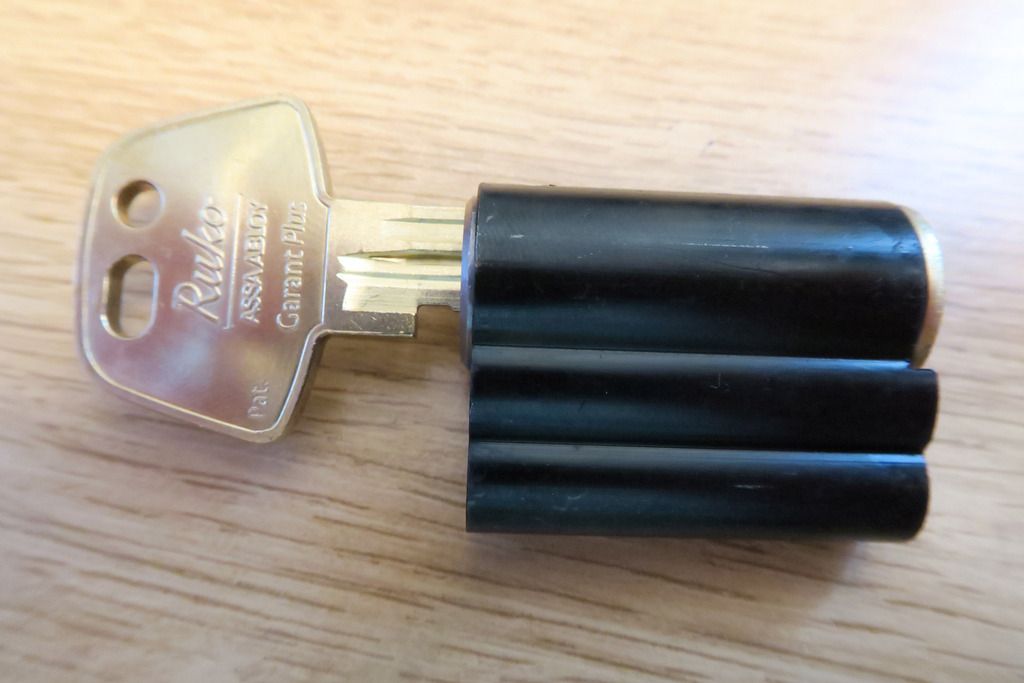
The Garant Plus keys are a golden-tinted-silver colour rather than the plain silver D12/1200 keys. They also have that cool laser track (though only the normal six bitting cuts):
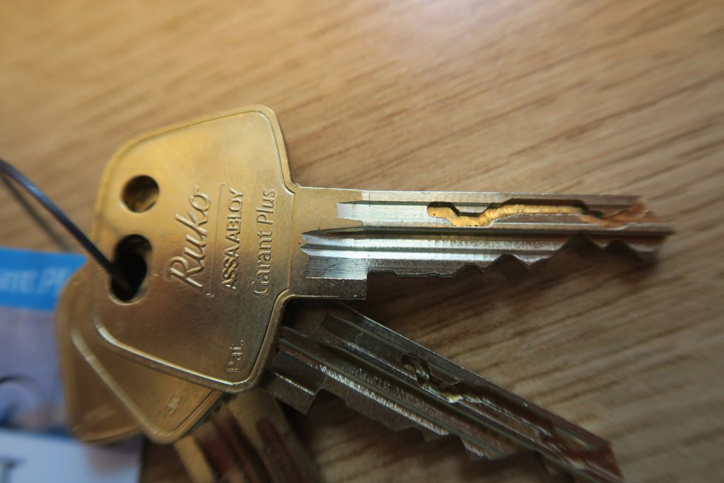
For some reason all the Ruko keys – 1200 series and Garant – have two holes in the top of the key bow for keyrings – a normal round hole (offset) and a longer oval one. I’m not 100% sure why.
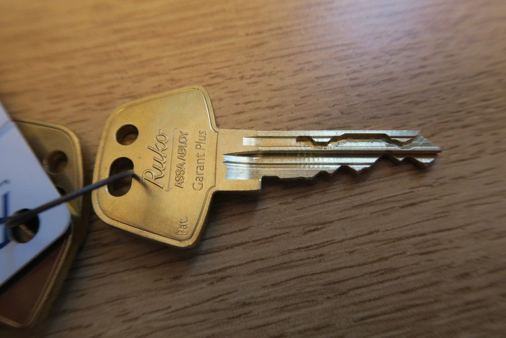
Another difference – the end of the plug / keyway entrance on 1200 series locks is a golden / brass colour, whereas the Garant Plus core has a gunmetal-grey finish. Not sure why the key and plug colours don’t match!
Shackle of the 2647 – 10mm, same as the 2646, but also longer like the 2643:
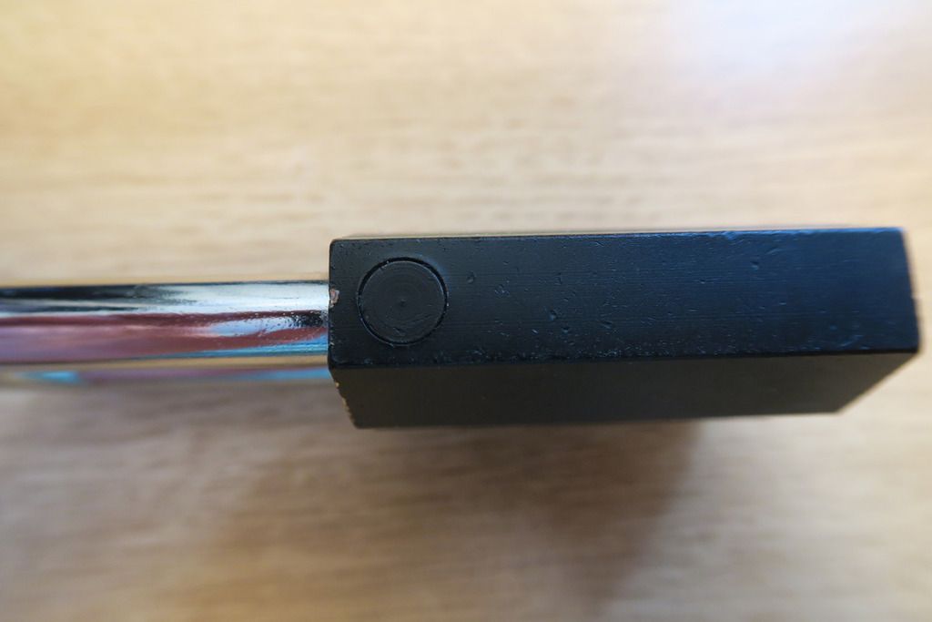
These locks all have that odd round plug in the body on the closed shackle side:
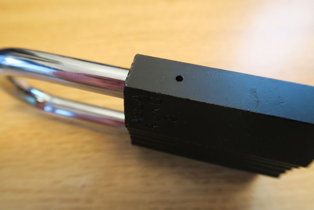
Drain hole on the opposite side:
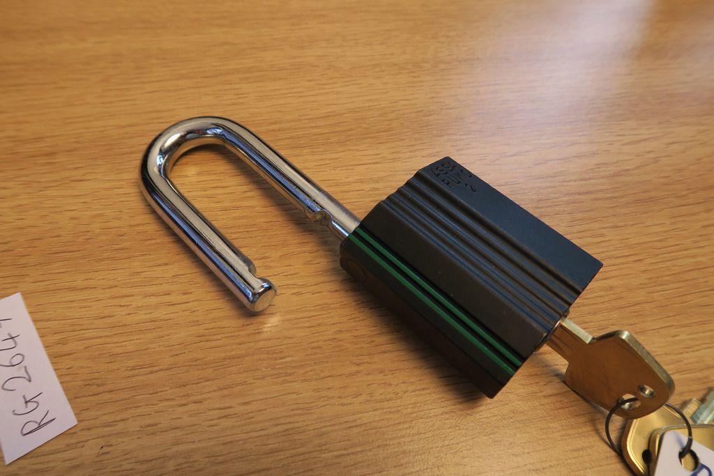
Unlocked:
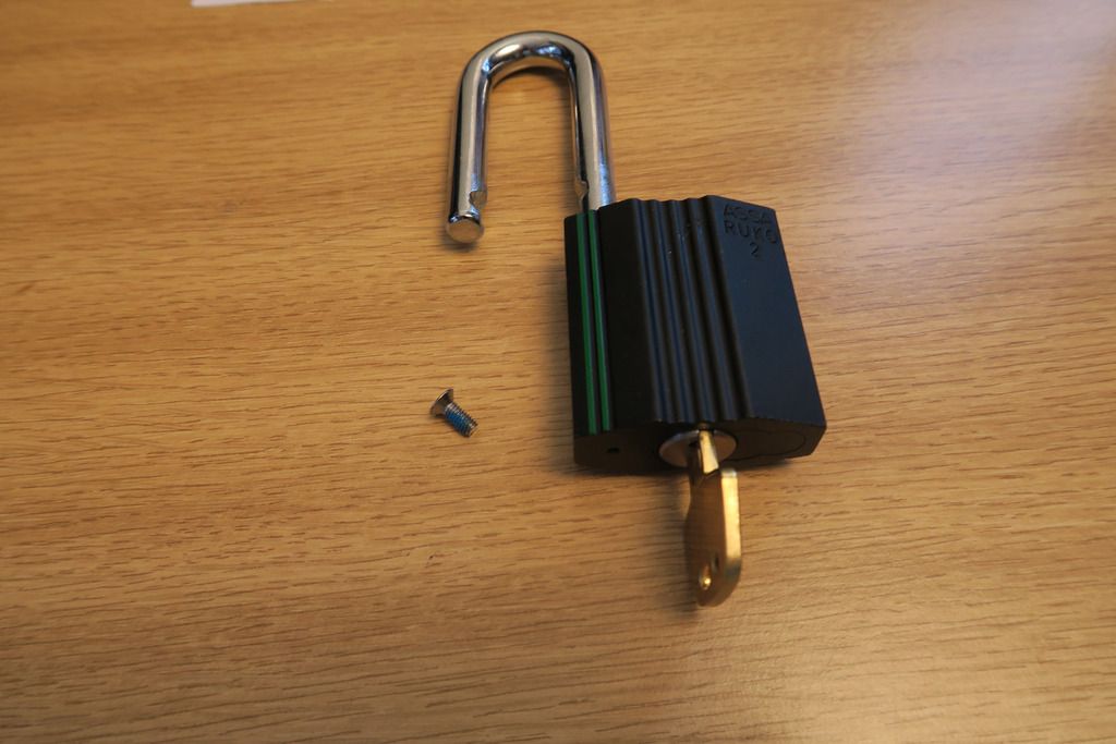
Screw removed:
The screw removal process is just the same as the other grade 2 Rukos, as is the actuating mechanism. You can put a Garant Plus or D12 or 500 or 600 series in here; it doesn’t matter too much:
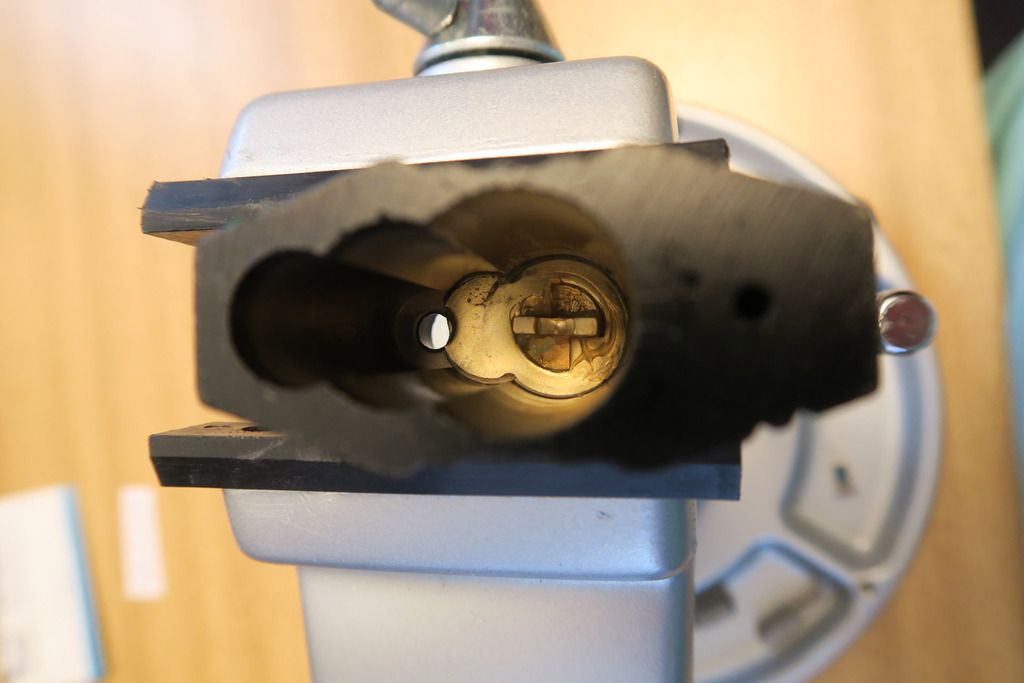
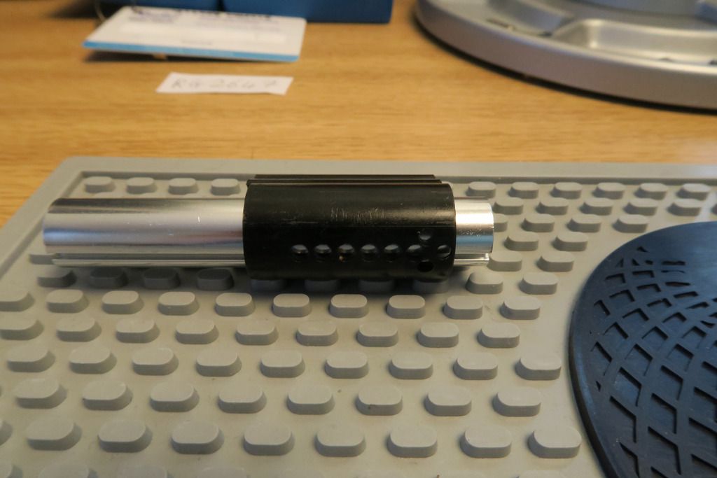
Garant Plus core removed:
Time to see what’s inside this bad boy! Same as the 1200 series, first remove the “Z” backplate...
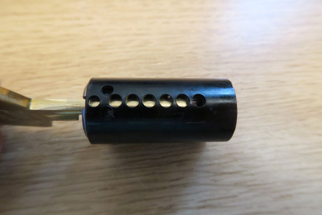
You can then see the reverse of the plug:
These cylinders to have these top loading holes for pins, but I’ve never really used them myself:
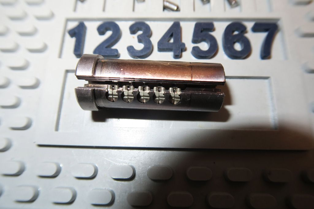
Pop out the plug...
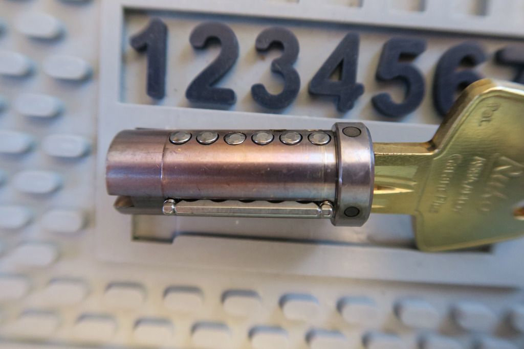
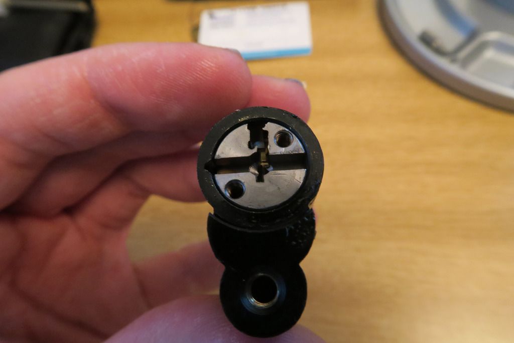
Two major differences we can see in the pic above – firstly, it has a sidebar (facing us). Secondly, the plug appears to have anti-drill pins on the key entrance bezel.
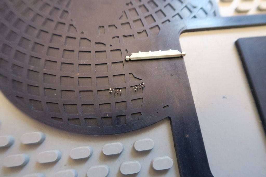
If we pop the sidebar out (so it doesn’t get lost) and flip the plug over (might be a wise idea to de-pin it too, which you’re at it!) you can see the side pins underneath:
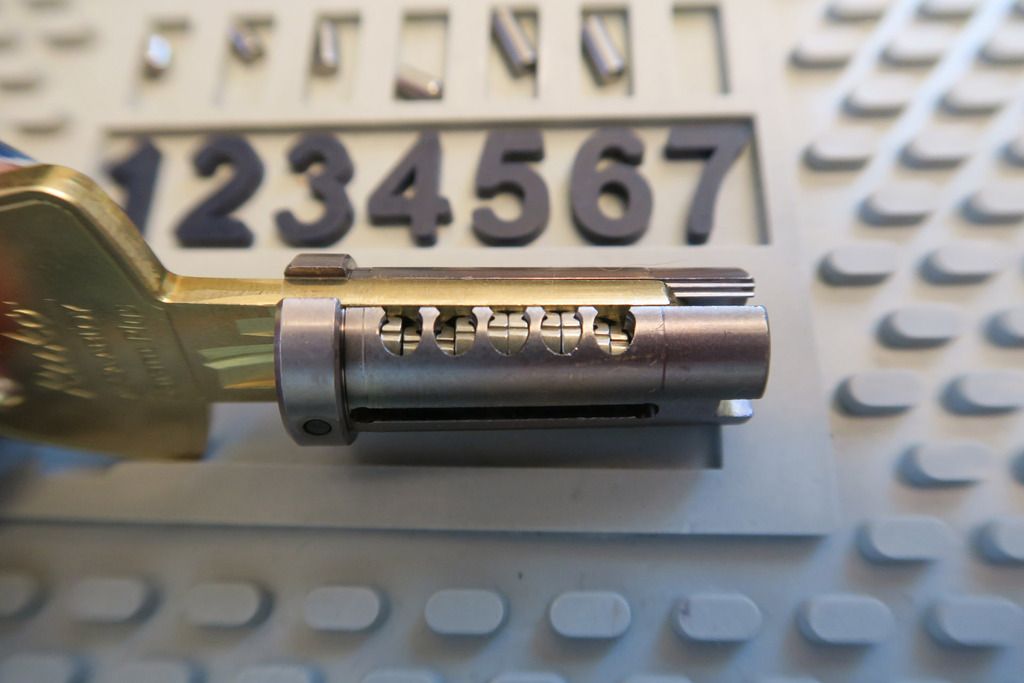
These are not actually removable and will not come out even if you remove the key. While there are technically 6 “pin holes”, each pin is actually two independent sliders, so there are a total of TEN sidebar pins plus the six normal pins that you’ll have to pick (these are active pins as they use a sidebar). Nice!
The sliders move up and down, and are moved along by the cut in the side of the key. When they are brought to the correct height, a slot in the side of the side pin will line up with a nub in the sidebar – and when all the slots and nubs line up, the sidebar can be depressed and will slot into the plug.
Sidebar and springs:
Pins – six standard key pins and six ASSA uhm.. Inverted spools, or whatever, for the drivers. If you didn’t see my ASSA Mogul post (which had the same pins), these have very fine and sharp outer edges, like a very thin-edged spool, then they dip down, but then come back up in the middle section. Basically they seem to be an ASSA thing. Quite cool! All the pins seem to be stainless steel, too. Weirdly the KEYS seem to be brass, which makes me think they’ll wear down much faster than the pins – maybe that’s intentional.
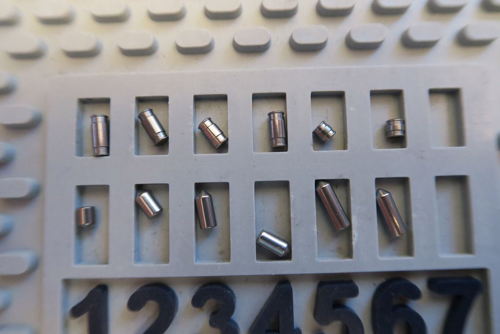
Pins and plug:
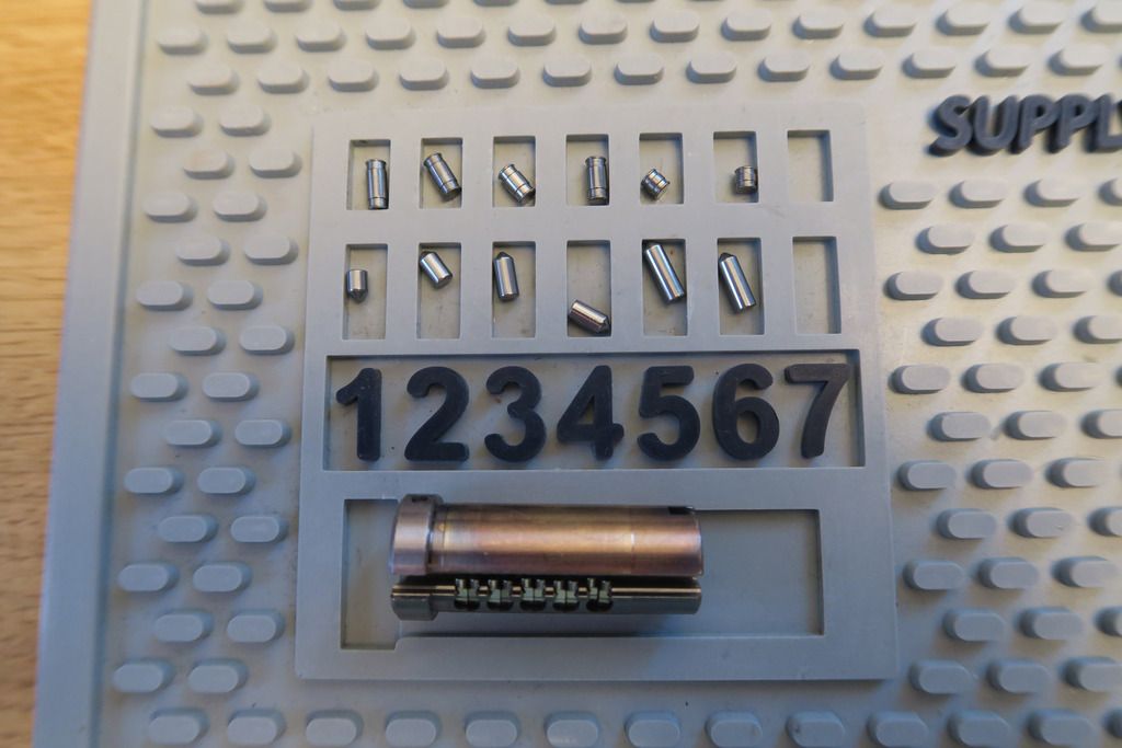
And we’re done with the first Garant Ruko! I won’t strip down any of the other Garant cylinders because they’ll be identical to this. I do love these Garant cores, though. Sixteen active pins to pick, dayum.
The 2647 takes the shackle length of the 2643 (52mm) and combines it with the shackle thickness of the RG2646 (10mm). Internally, the lock is still the same as the 2641 (and really all other green stripe / grade 2 Rukos, except the shutter lock), however it differs from the 2641 in that the shackle is both longer and thicker. This is the last such identically-bodied grade 2 Ruko padlock that we’ll be looking at.
Of course, this one also has a different core, so we’ll be stripping that down in this post!

The Garant Plus core also comes with a snazzy credit-card sized code card complete with a bank-pin-letter style obfuscation label which is pretty cool.

Close-up of the new code card:

The Garant Plus keys are a golden-tinted-silver colour rather than the plain silver D12/1200 keys. They also have that cool laser track (though only the normal six bitting cuts):

For some reason all the Ruko keys – 1200 series and Garant – have two holes in the top of the key bow for keyrings – a normal round hole (offset) and a longer oval one. I’m not 100% sure why.

Another difference – the end of the plug / keyway entrance on 1200 series locks is a golden / brass colour, whereas the Garant Plus core has a gunmetal-grey finish. Not sure why the key and plug colours don’t match!

Shackle of the 2647 – 10mm, same as the 2646, but also longer like the 2643:

These locks all have that odd round plug in the body on the closed shackle side:

Drain hole on the opposite side:

Unlocked:

Screw removed:

The screw removal process is just the same as the other grade 2 Rukos, as is the actuating mechanism. You can put a Garant Plus or D12 or 500 or 600 series in here; it doesn’t matter too much:

Garant Plus core removed:

Time to see what’s inside this bad boy! Same as the 1200 series, first remove the “Z” backplate...

You can then see the reverse of the plug:

These cylinders to have these top loading holes for pins, but I’ve never really used them myself:

Pop out the plug...


Two major differences we can see in the pic above – firstly, it has a sidebar (facing us). Secondly, the plug appears to have anti-drill pins on the key entrance bezel.
If we pop the sidebar out (so it doesn’t get lost) and flip the plug over (might be a wise idea to de-pin it too, which you’re at it!) you can see the side pins underneath:

These are not actually removable and will not come out even if you remove the key. While there are technically 6 “pin holes”, each pin is actually two independent sliders, so there are a total of TEN sidebar pins plus the six normal pins that you’ll have to pick (these are active pins as they use a sidebar). Nice!

The sliders move up and down, and are moved along by the cut in the side of the key. When they are brought to the correct height, a slot in the side of the side pin will line up with a nub in the sidebar – and when all the slots and nubs line up, the sidebar can be depressed and will slot into the plug.
Sidebar and springs:

Pins – six standard key pins and six ASSA uhm.. Inverted spools, or whatever, for the drivers. If you didn’t see my ASSA Mogul post (which had the same pins), these have very fine and sharp outer edges, like a very thin-edged spool, then they dip down, but then come back up in the middle section. Basically they seem to be an ASSA thing. Quite cool! All the pins seem to be stainless steel, too. Weirdly the KEYS seem to be brass, which makes me think they’ll wear down much faster than the pins – maybe that’s intentional.

Pins and plug:

And we’re done with the first Garant Ruko! I won’t strip down any of the other Garant cylinders because they’ll be identical to this. I do love these Garant cores, though. Sixteen active pins to pick, dayum.


