


![]() Wed Dec 25, 2013 12:11 pm
Wed Dec 25, 2013 12:11 pm
Mechanical Breakdown of a KABA MAS X09 Safe Lock
Mechanical Breakdown of a KABA MAS X-09
Had these pics for a while. About time I did something with them.
This is not a full explanation of the workings, and it looks that I did not take much in the way of pictures of the outside area of the lock. Please excuse the incorrect terminology for the parts, as I am only lightly familiar with this lock.
Here we will be breaking down this excellent lock. My thanks to a fellow member who has requested to remain nameless who allowed me to photograph this lock, to my good friend Bruce, who gave me a drilled (useless) lock to fully disassemble and figure out the mechanical workings. Any serial numbers you see on this pictorial are from the drilled lock to protect the working lock.
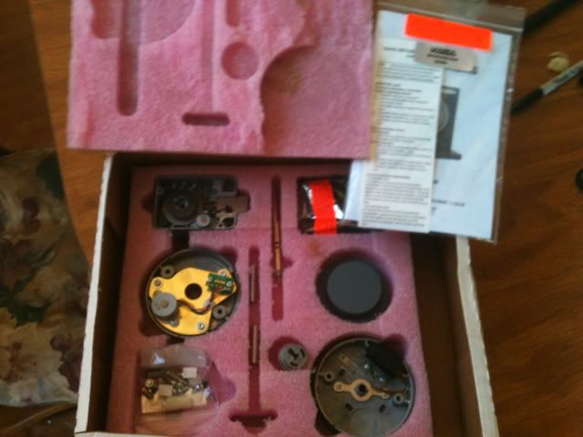
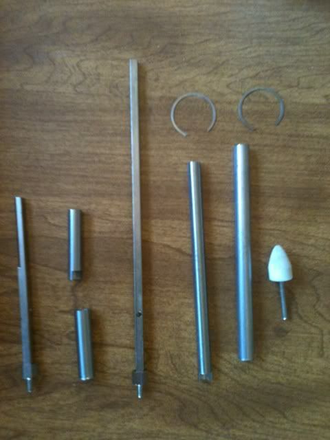
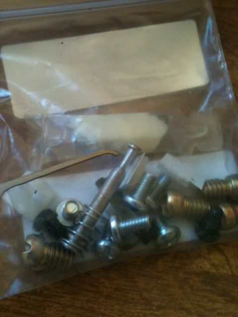
Anyway, here are the components. (The box is not original, but you see the parts better).
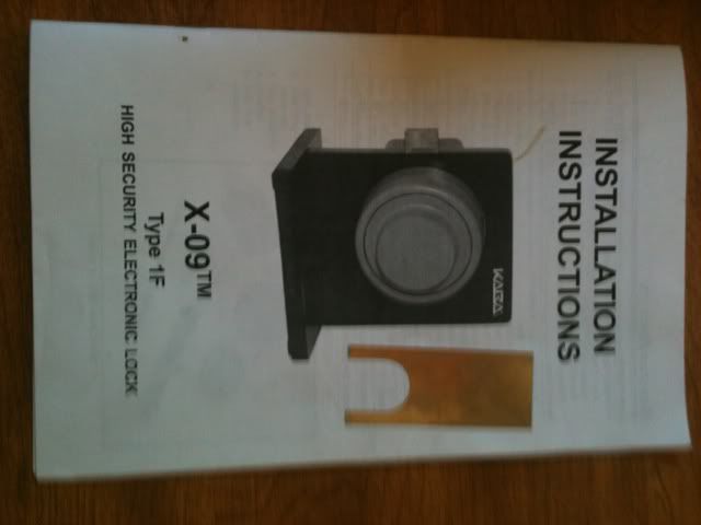
Here is an original boxed set.
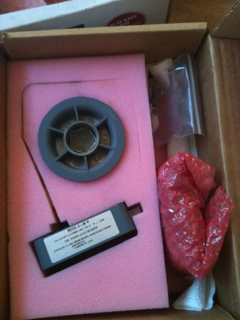
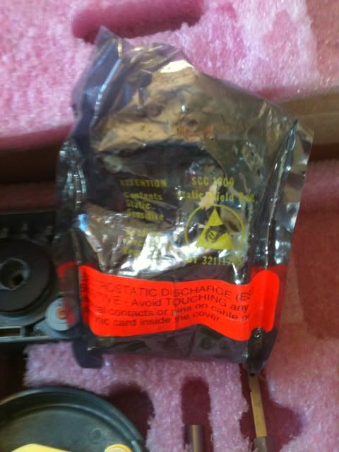
The main circuit board is integrated with the lock cover, and comes in a static bag.
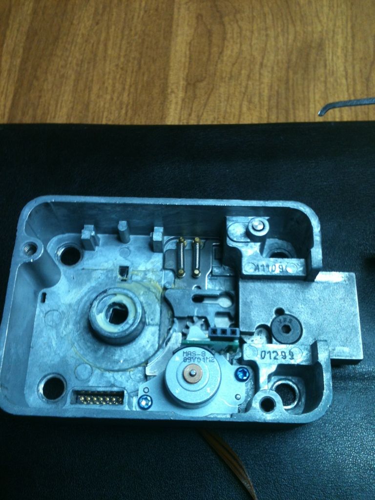
The actual circuit board looks like this:
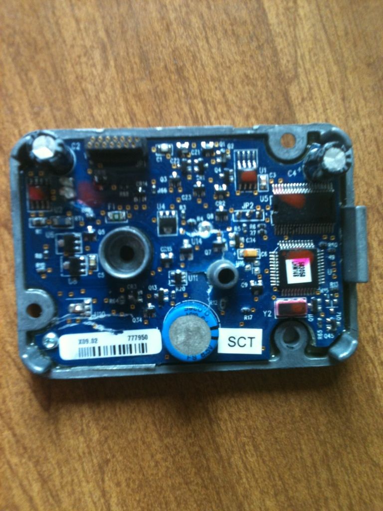
In the lower left corner, you can see the serial number.
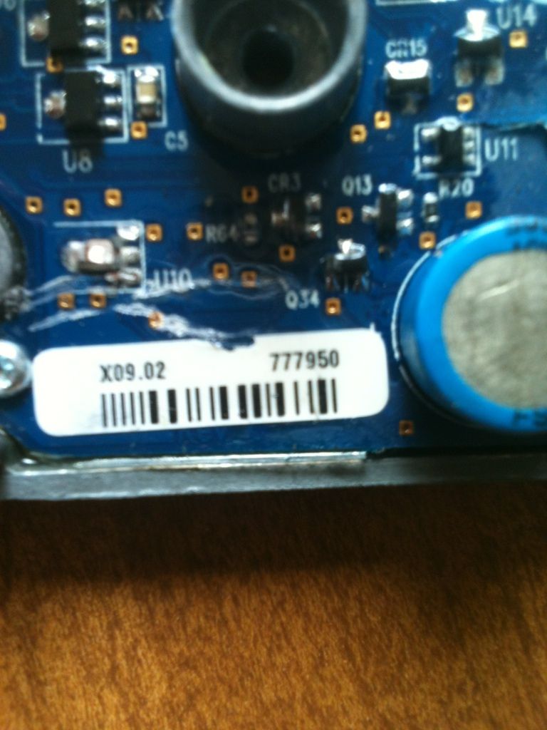
The serial number is the number to the right on the sticker. To the left, is the model (X09) and the year of manufacture (02).
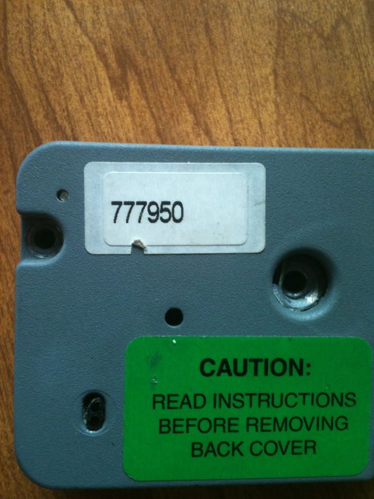
The outside of the box might (but should not) have a sticker with the serial number as well. The reason it should not have the serial number placed on the outside of the lock body is because if someone can see that number (don't want to go into destructive entry), they can use it to get into the lock. Will explain that in another writeup soon.
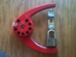
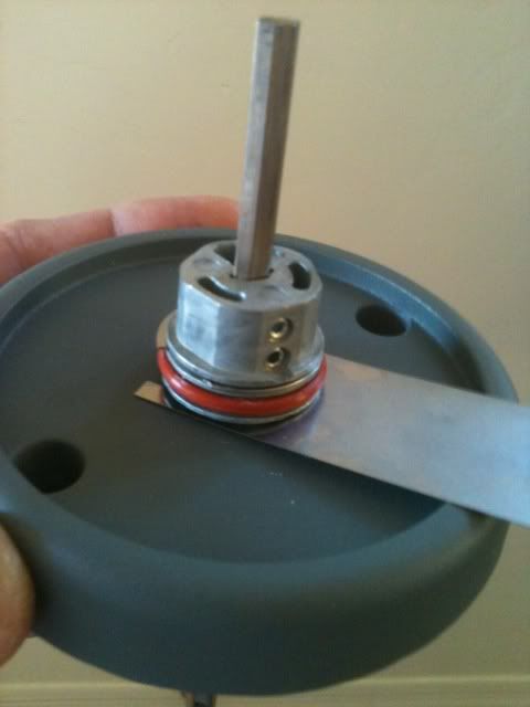
The dial spindle and spindle tubes can come in two sizes. The standard are the longer ones in this picture, but the shorter ones come with locks set up for filing cabinets and thin doors. The white Dremel tool is for deburring the cut ends of the tubes before assembly.
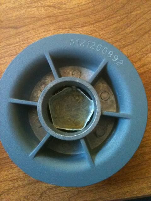
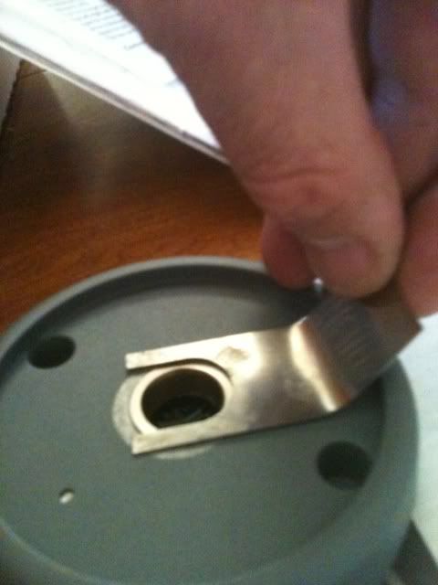
On the outside of the door, this secures to the spindle, and the dial gets pressed onto it. The clip retains the dial. Have one installed on this part, and another beside it for an example.
And the inside of the dial that is press fit onto the above part.
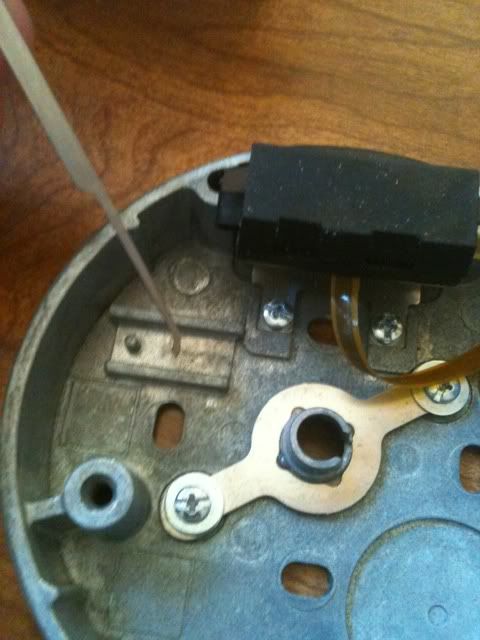
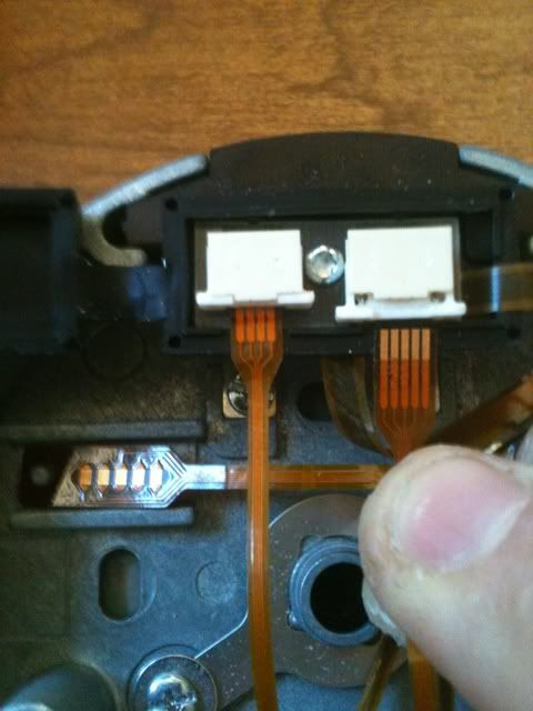
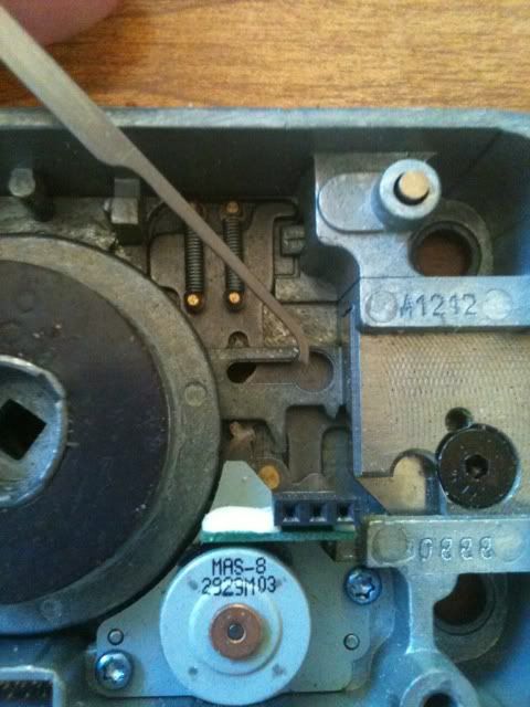
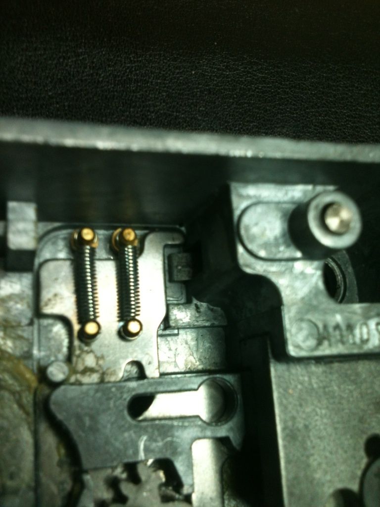
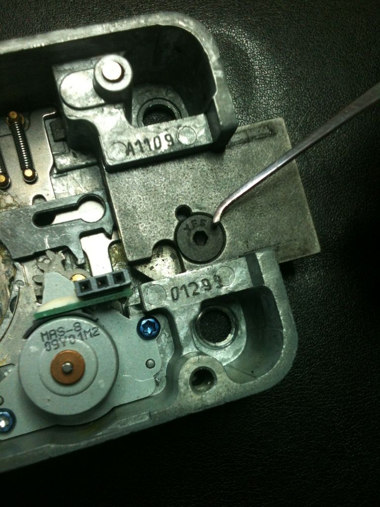
There are three ribbon cables that are used for power, data, and opening on this lock. One fits here where the pick is pointing. The large rubber block looking thing at the top of the picture is opened to show where the other two cables attach.
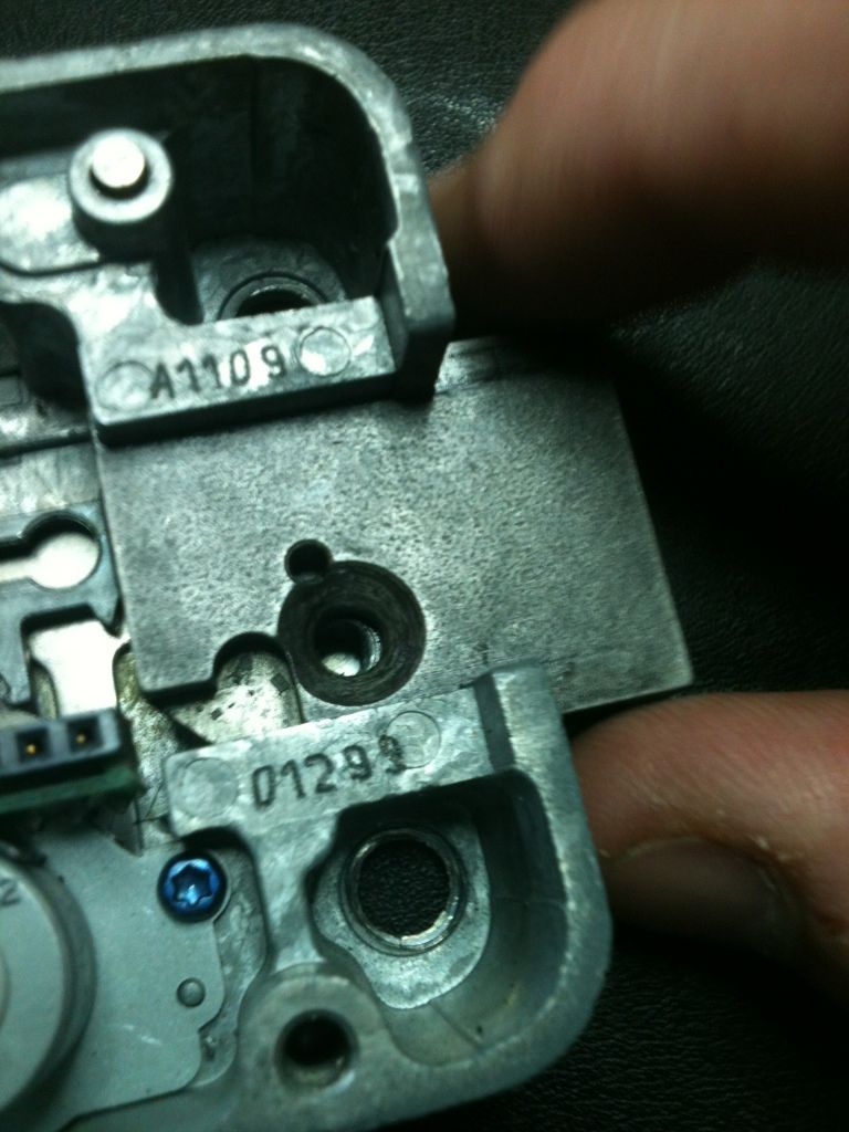
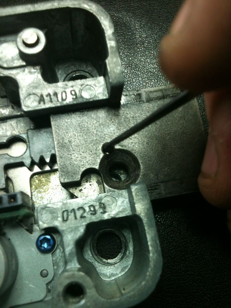
Here is where the other two cables go. The one on the left has the retainer clip open for installation and removal of the cable, the one on the right is closed, to secure the cable in place.
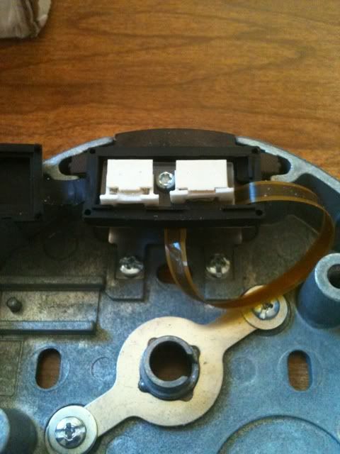
The cables in place. That cable on the right is facing the wrong way - shiny side should go down. Took the picture this way so you could see the shiny side. The other cables are correct.
The lock comes with this spacer, to allow correct clearance and operation of the dial mount.
It is used like this: give the spacer a slight bend to allow it to stay flat. Since this lock was new, did not bend it for this picture.
Here is another of those spacers, correctly bent.
You would then mark the spindle for the correct length (flush with top of this part), remove and cut it, and reinstall it, tightening those Allen head set screws.
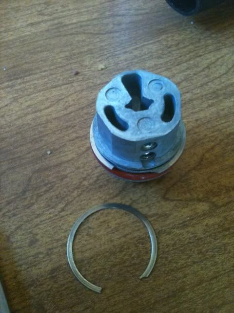
You see this part inside the lock body...
That is used to capture this part, which is attached to the lock cover, keeping the lock cover from being removed unless the bolt is in the correct position.
Have the parts related to the spindle removed so we can see the mechanical parts of the lock.
Relocker button, normally held down by the lock cover.
It presses down on one side of a lever, the other side of which is this side that actually blocks operation.
When pressed down, you can see the other lower part is raised, so as to not block operation.
Held up the relocker, then used a pick to move the sliding part down so you can see where the relocker would be located when the lock operates.
And if it was blocked.
This screw retains the bolt
Once the screw is taken out, the bolt can be removed...
Once the spring loaded bearing inside this hole is depressed.
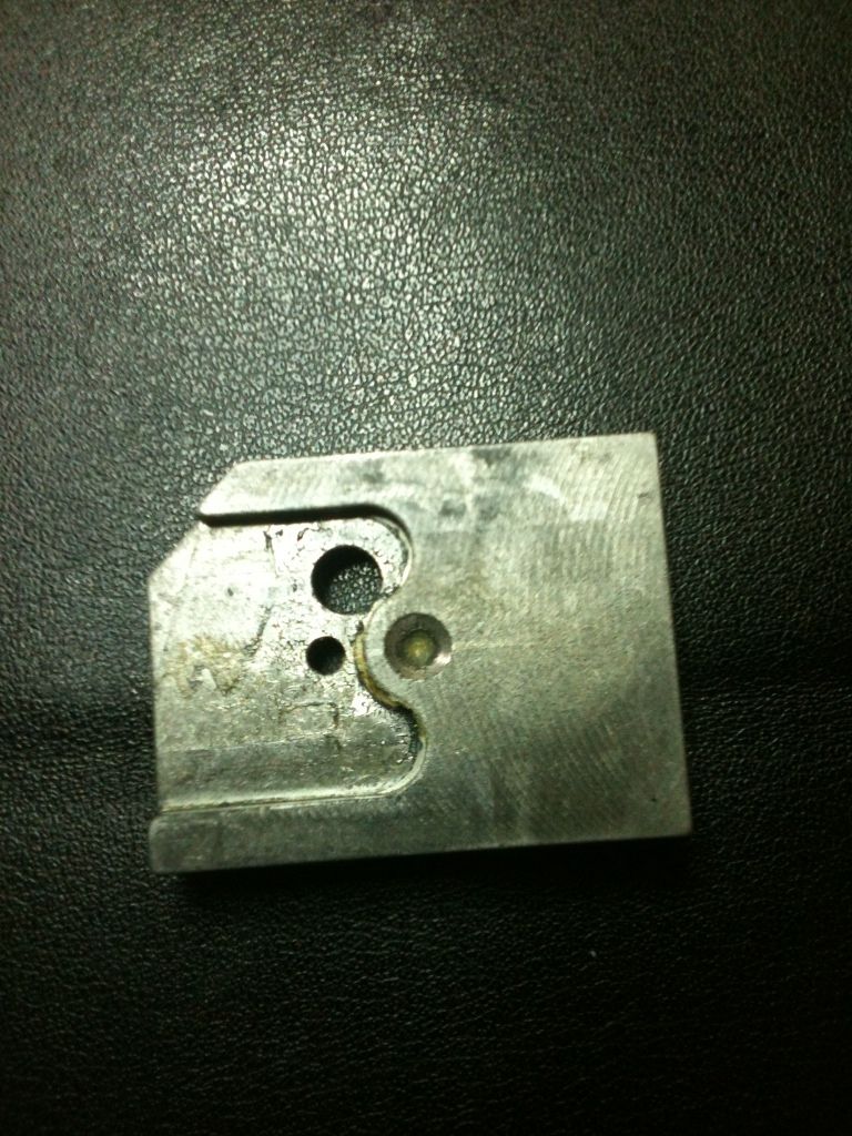
The bolt.
This is the spring loaded bearing that was depressed. It feels much best now. :mrgreen:
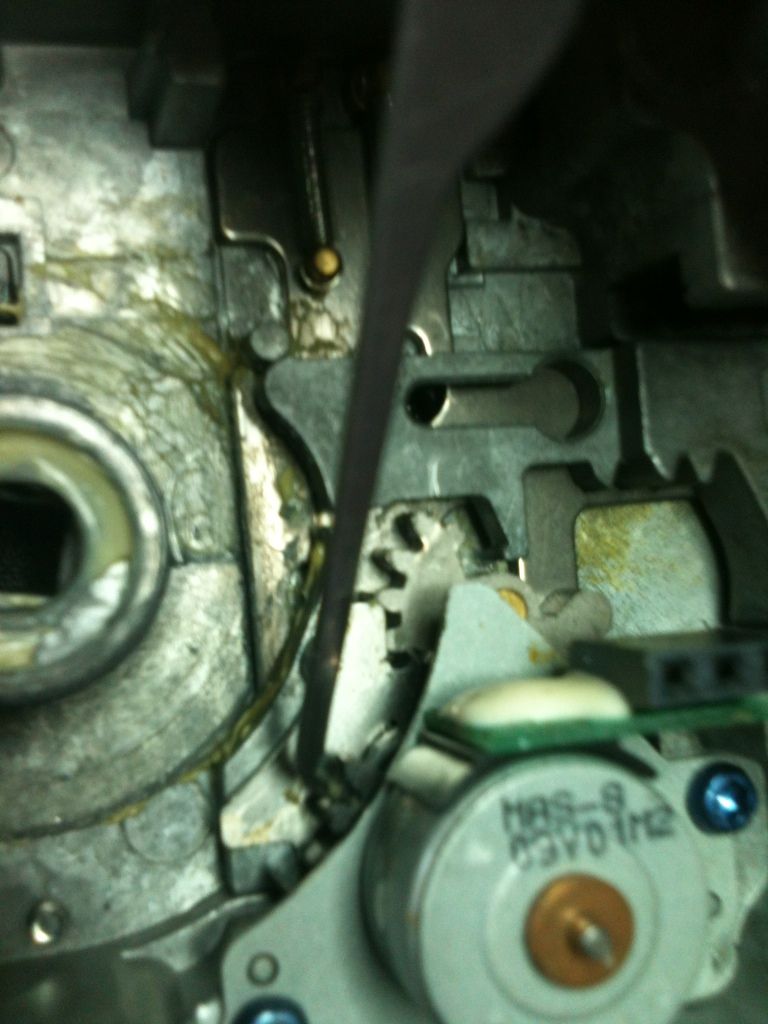
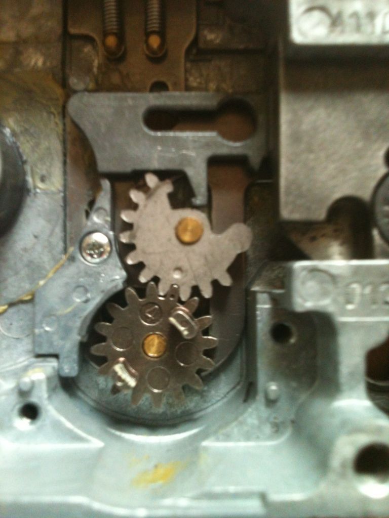
Here, there is a gear, the first tooth of which can be seen here. Notice the arm pressing against the cam above, near the rounded point of the triangle.
Here, the gear is moved a little, and the arm is pulling away from the cam above.
And almost fully moved.
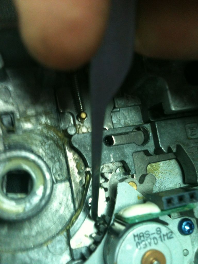
Here you can see that with the gear at the above point, the sliding part can pass the relocker if the cover is in place. Now the gear can continue and move the actuator, retracting the bolt.
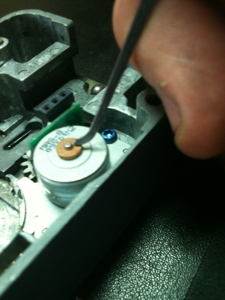
The motor also moves in and out, so just applying power to one spot will make the motor turn, but will not open the lock as the gears will not line up.
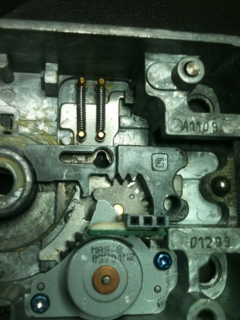
At rest:
Powered up correctly
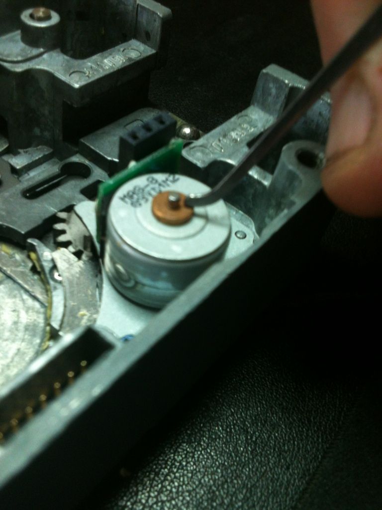
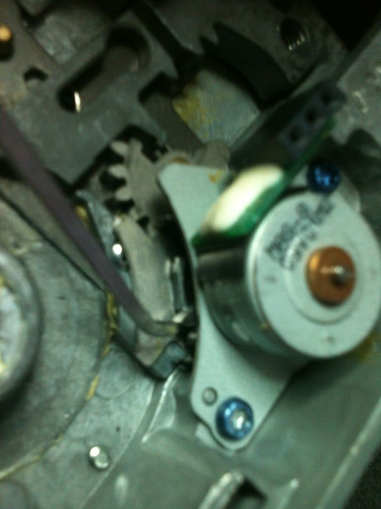
The motor removed, so you can see the gear:
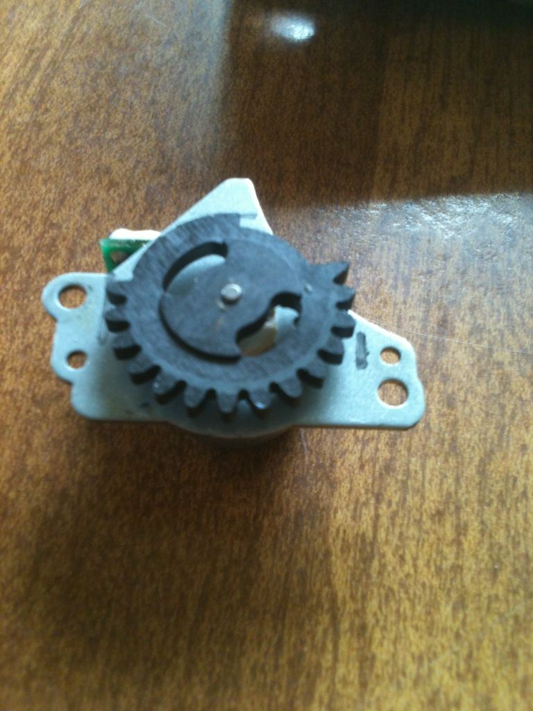
The motor at rest...
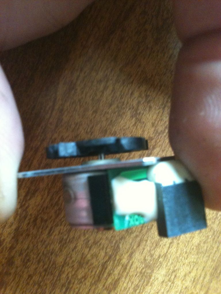
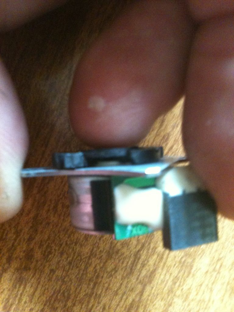
And in 'powered' position
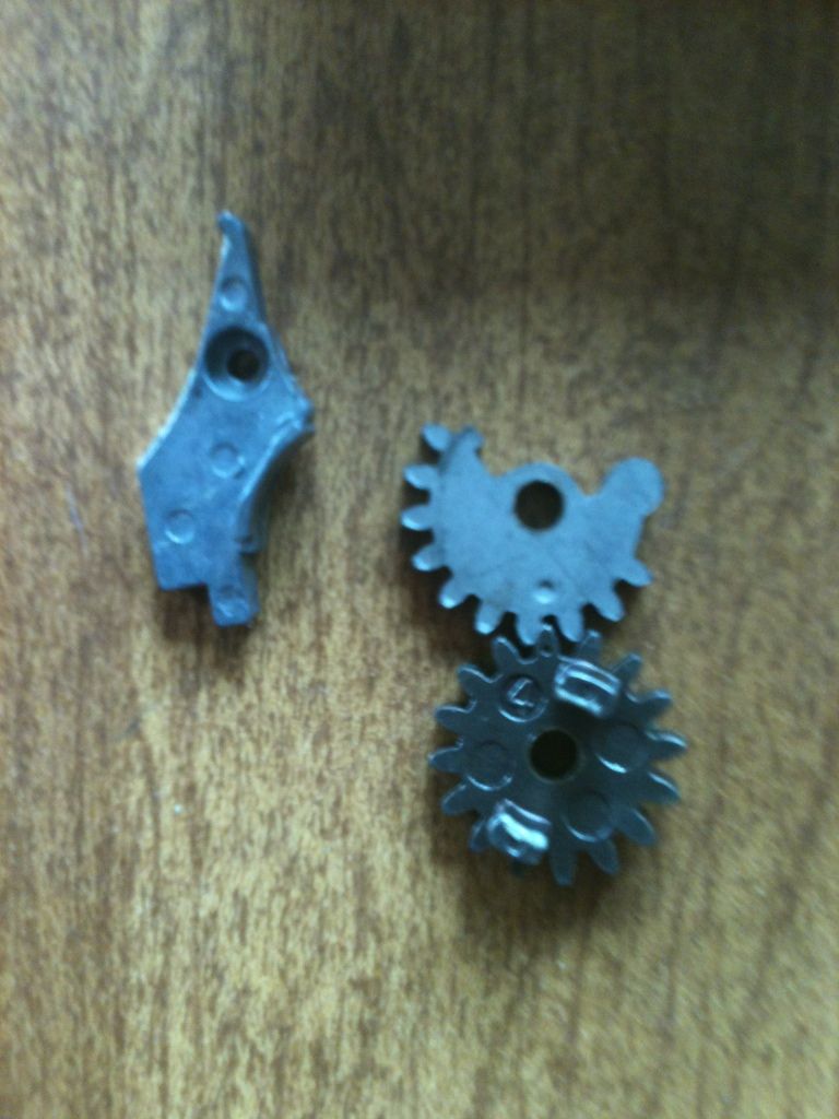
The motor/gear assembly removed, can see a cover plate.
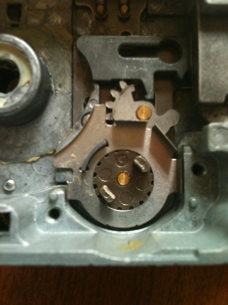
With the cover plate removed, you can see the other gears below.
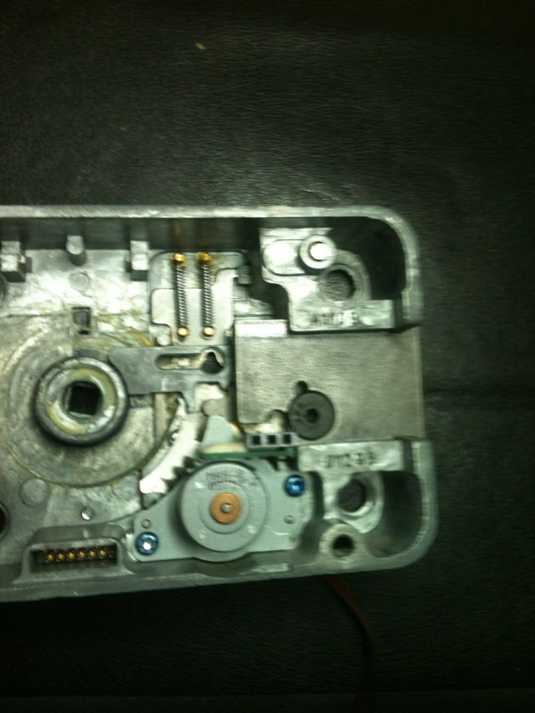
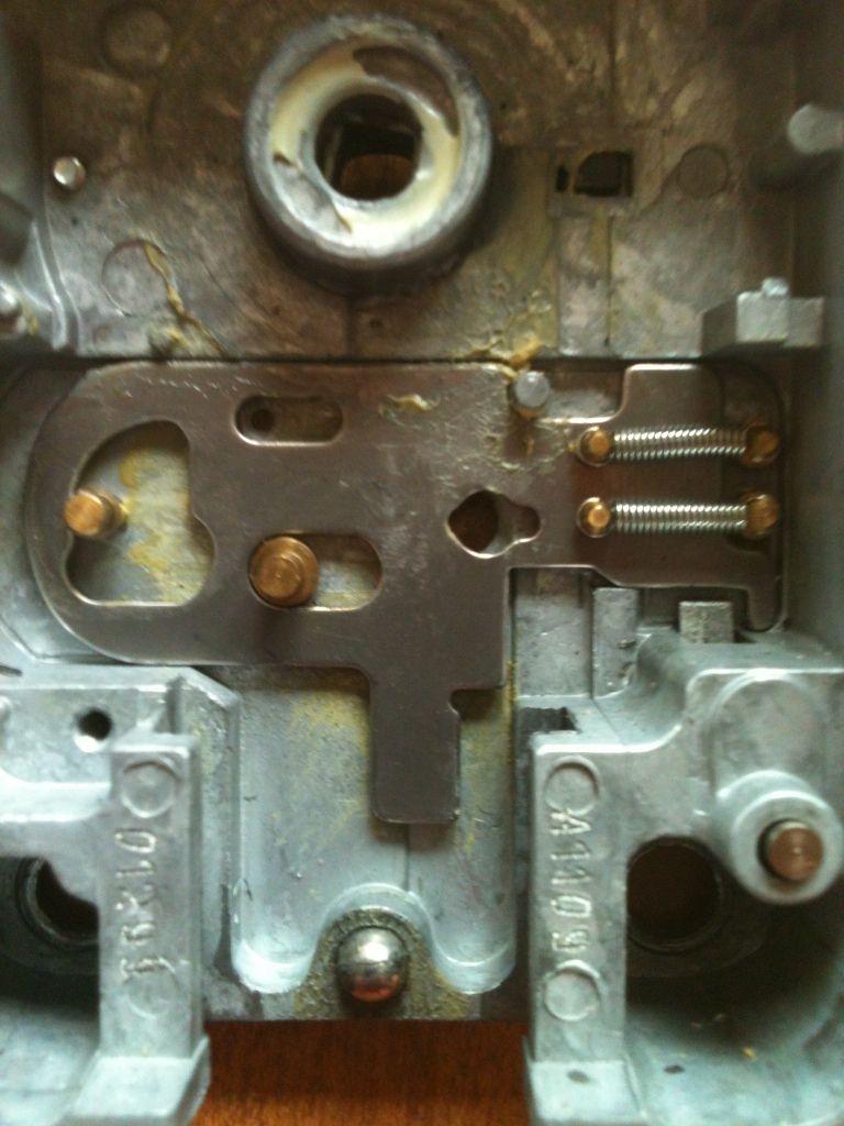
With the bolt fully retracted, the parts of the actuator and the sliding part line up the holes that would release the pin keeping the back cover in place, allowing the lock to be taken apart.
With the bolt in place, so you can see the above parts and bolt retracted.
The relocking slider
This ends the pictures I took of the mechanical parts of the X-09. Hope you learned something, or at least had some curiosity satisfied.
Gordon
Had these pics for a while. About time I did something with them.
This is not a full explanation of the workings, and it looks that I did not take much in the way of pictures of the outside area of the lock. Please excuse the incorrect terminology for the parts, as I am only lightly familiar with this lock.
Here we will be breaking down this excellent lock. My thanks to a fellow member who has requested to remain nameless who allowed me to photograph this lock, to my good friend Bruce, who gave me a drilled (useless) lock to fully disassemble and figure out the mechanical workings. Any serial numbers you see on this pictorial are from the drilled lock to protect the working lock.
Anyway, here are the components. (The box is not original, but you see the parts better).
Here is an original boxed set.
The main circuit board is integrated with the lock cover, and comes in a static bag.
The actual circuit board looks like this:
In the lower left corner, you can see the serial number.
The serial number is the number to the right on the sticker. To the left, is the model (X09) and the year of manufacture (02).
The outside of the box might (but should not) have a sticker with the serial number as well. The reason it should not have the serial number placed on the outside of the lock body is because if someone can see that number (don't want to go into destructive entry), they can use it to get into the lock. Will explain that in another writeup soon.
The dial spindle and spindle tubes can come in two sizes. The standard are the longer ones in this picture, but the shorter ones come with locks set up for filing cabinets and thin doors. The white Dremel tool is for deburring the cut ends of the tubes before assembly.
On the outside of the door, this secures to the spindle, and the dial gets pressed onto it. The clip retains the dial. Have one installed on this part, and another beside it for an example.
And the inside of the dial that is press fit onto the above part.
There are three ribbon cables that are used for power, data, and opening on this lock. One fits here where the pick is pointing. The large rubber block looking thing at the top of the picture is opened to show where the other two cables attach.
Here is where the other two cables go. The one on the left has the retainer clip open for installation and removal of the cable, the one on the right is closed, to secure the cable in place.
The cables in place. That cable on the right is facing the wrong way - shiny side should go down. Took the picture this way so you could see the shiny side. The other cables are correct.
The lock comes with this spacer, to allow correct clearance and operation of the dial mount.
It is used like this: give the spacer a slight bend to allow it to stay flat. Since this lock was new, did not bend it for this picture.
Here is another of those spacers, correctly bent.
You would then mark the spindle for the correct length (flush with top of this part), remove and cut it, and reinstall it, tightening those Allen head set screws.
You see this part inside the lock body...
That is used to capture this part, which is attached to the lock cover, keeping the lock cover from being removed unless the bolt is in the correct position.
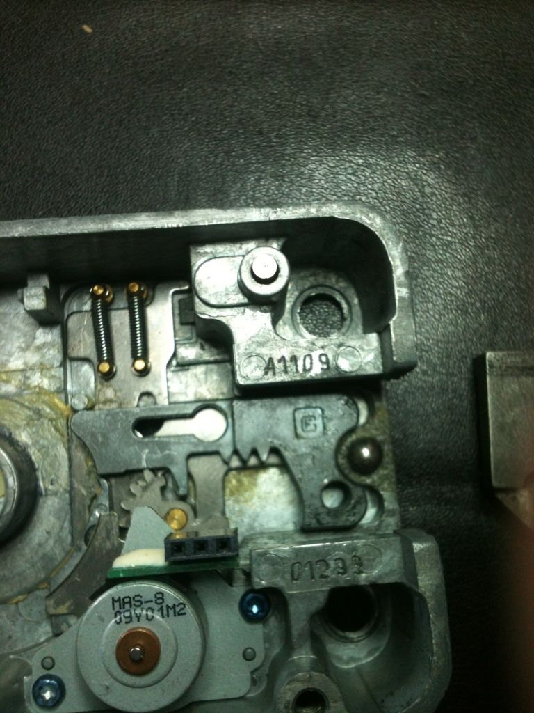
Have the parts related to the spindle removed so we can see the mechanical parts of the lock.
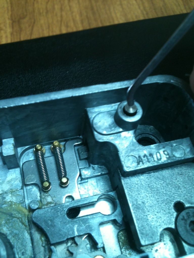
Relocker button, normally held down by the lock cover.
It presses down on one side of a lever, the other side of which is this side that actually blocks operation.
When pressed down, you can see the other lower part is raised, so as to not block operation.
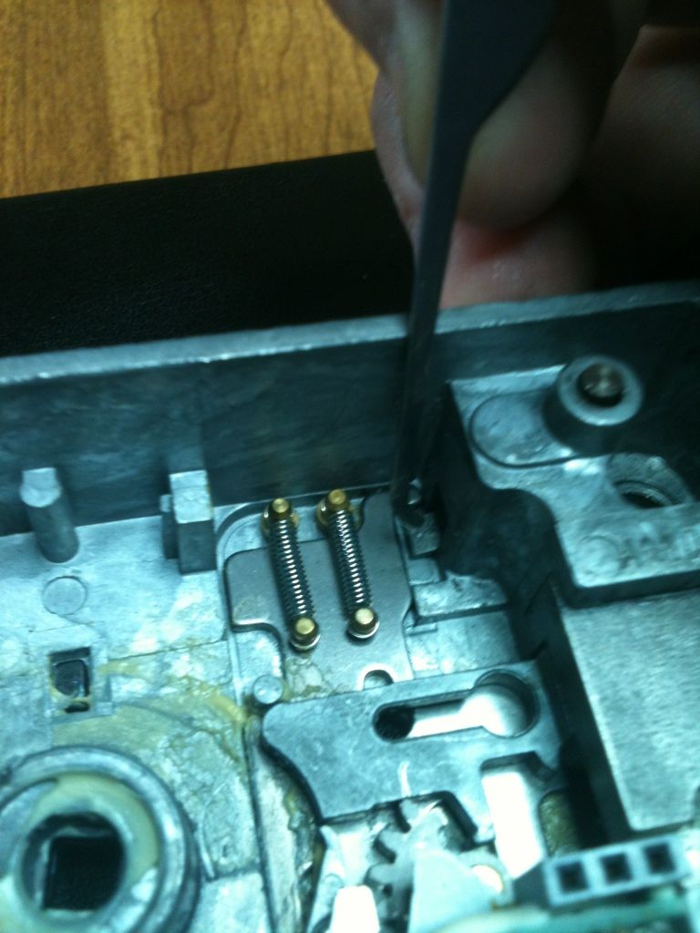
Held up the relocker, then used a pick to move the sliding part down so you can see where the relocker would be located when the lock operates.
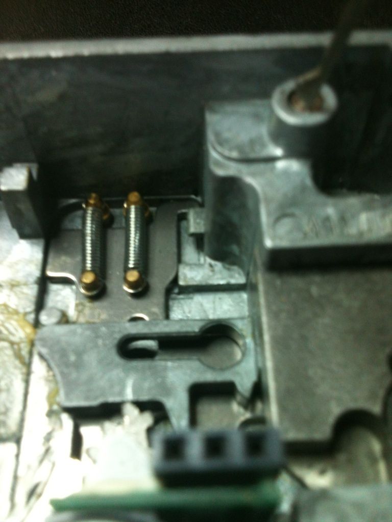
And if it was blocked.
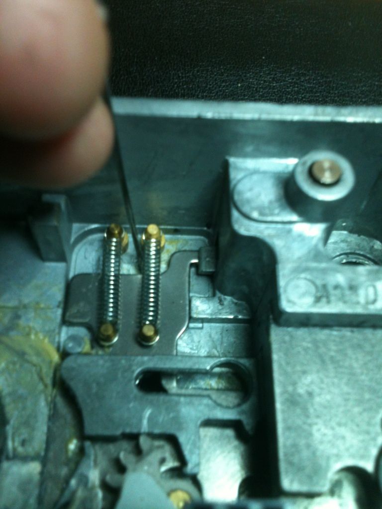
This screw retains the bolt
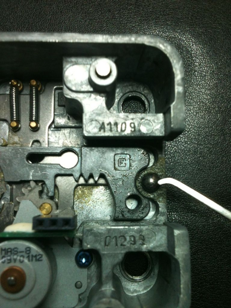
Once the screw is taken out, the bolt can be removed...
Once the spring loaded bearing inside this hole is depressed.
The bolt.
This is the spring loaded bearing that was depressed. It feels much best now. :mrgreen:
Here, there is a gear, the first tooth of which can be seen here. Notice the arm pressing against the cam above, near the rounded point of the triangle.
Here, the gear is moved a little, and the arm is pulling away from the cam above.
And almost fully moved.
Here you can see that with the gear at the above point, the sliding part can pass the relocker if the cover is in place. Now the gear can continue and move the actuator, retracting the bolt.
The motor also moves in and out, so just applying power to one spot will make the motor turn, but will not open the lock as the gears will not line up.
At rest:
Powered up correctly
The motor removed, so you can see the gear:
The motor at rest...
And in 'powered' position
The motor/gear assembly removed, can see a cover plate.
With the cover plate removed, you can see the other gears below.
With the bolt fully retracted, the parts of the actuator and the sliding part line up the holes that would release the pin keeping the back cover in place, allowing the lock to be taken apart.
With the bolt in place, so you can see the above parts and bolt retracted.
The relocking slider
This ends the pictures I took of the mechanical parts of the X-09. Hope you learned something, or at least had some curiosity satisfied.
Gordon
Just when you think you've learned it all, that is when you find you haven't learned anything yet.