


![]() Sat Nov 30, 2013 6:35 pm
Sat Nov 30, 2013 6:35 pm
Fixing a Fichet 787 (Very Picture Heavy)
Breakdown of a Fichet 787
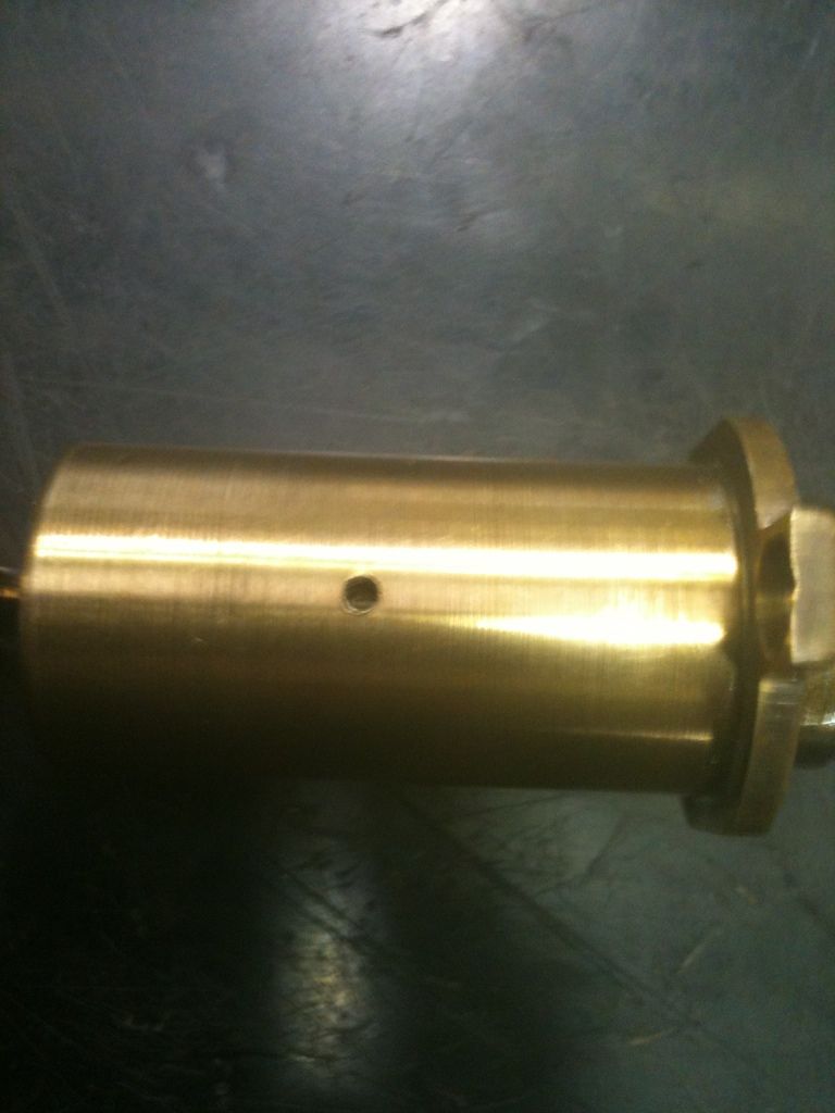
Won two of these from the same lockset (inner and outer) on eBay a while back. The inner lock worked great, but the outer one (this one) did not work. Finally had some time today at work to disassemble it to find out why it did not work.
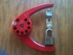
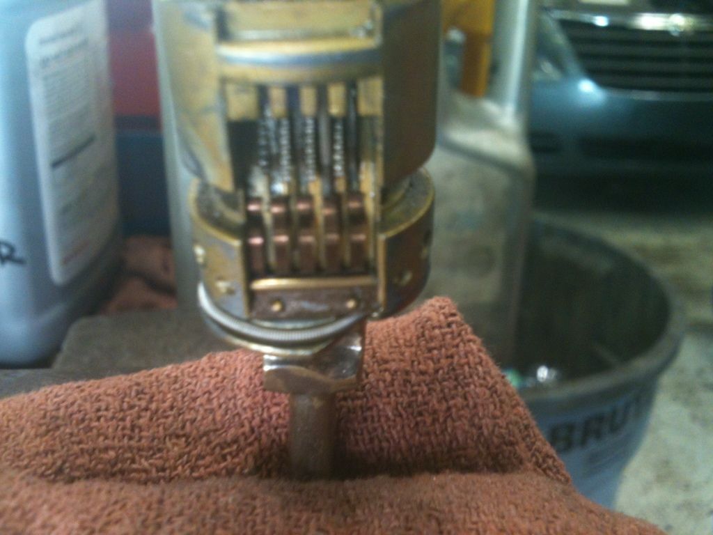
First, had to drill out the two hardened steel pins they used on the outer lock housing so we (you and I) could take a look inside. Since they were hardened steel pins, they laughed at my drill bits. Out came the diamond dremel bits. Who is your daddy, now?
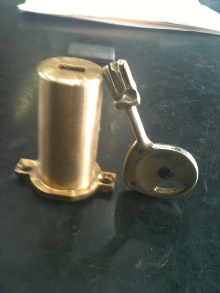
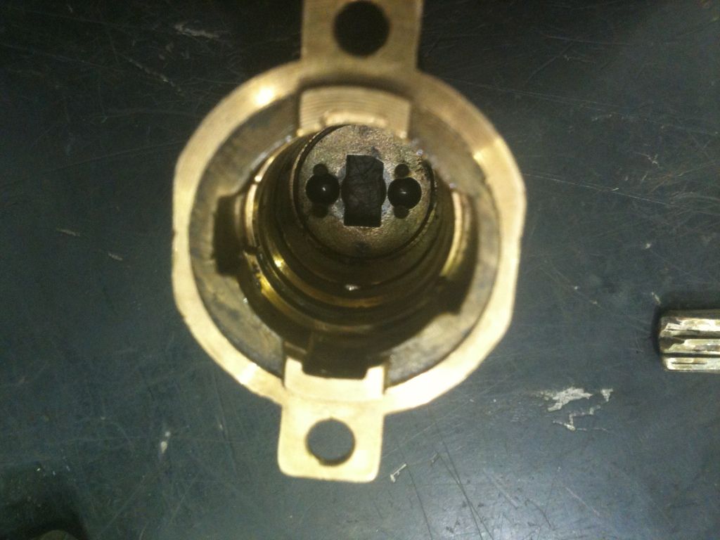
Now you can push the lock cylinder out of the housing:
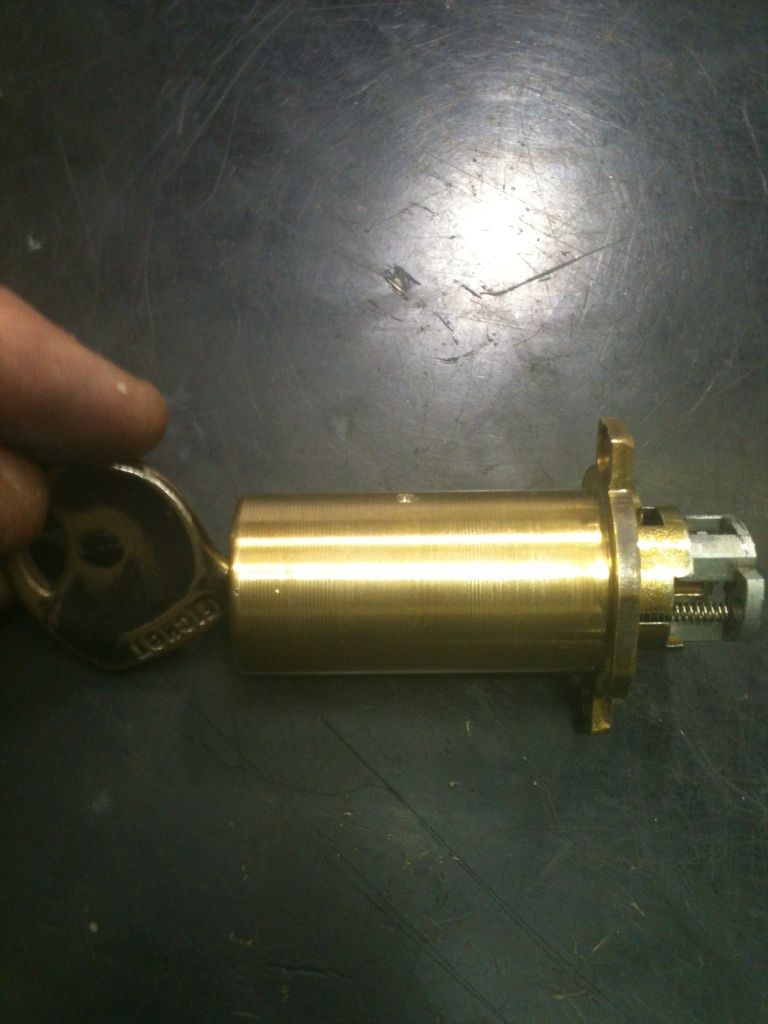
 No, you can't. The lock is key retaining, and the key bow will not fit through the keyhole in the housing.
Remove the key, then use a thin screwdriver or straight tool to push the lock cylinder out.
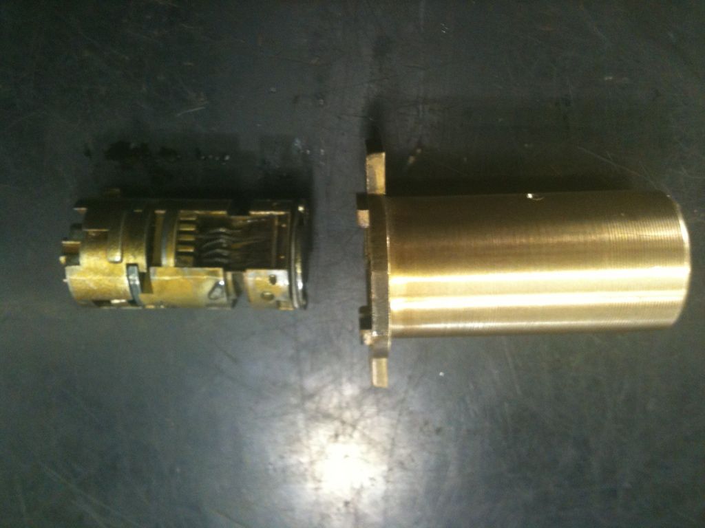
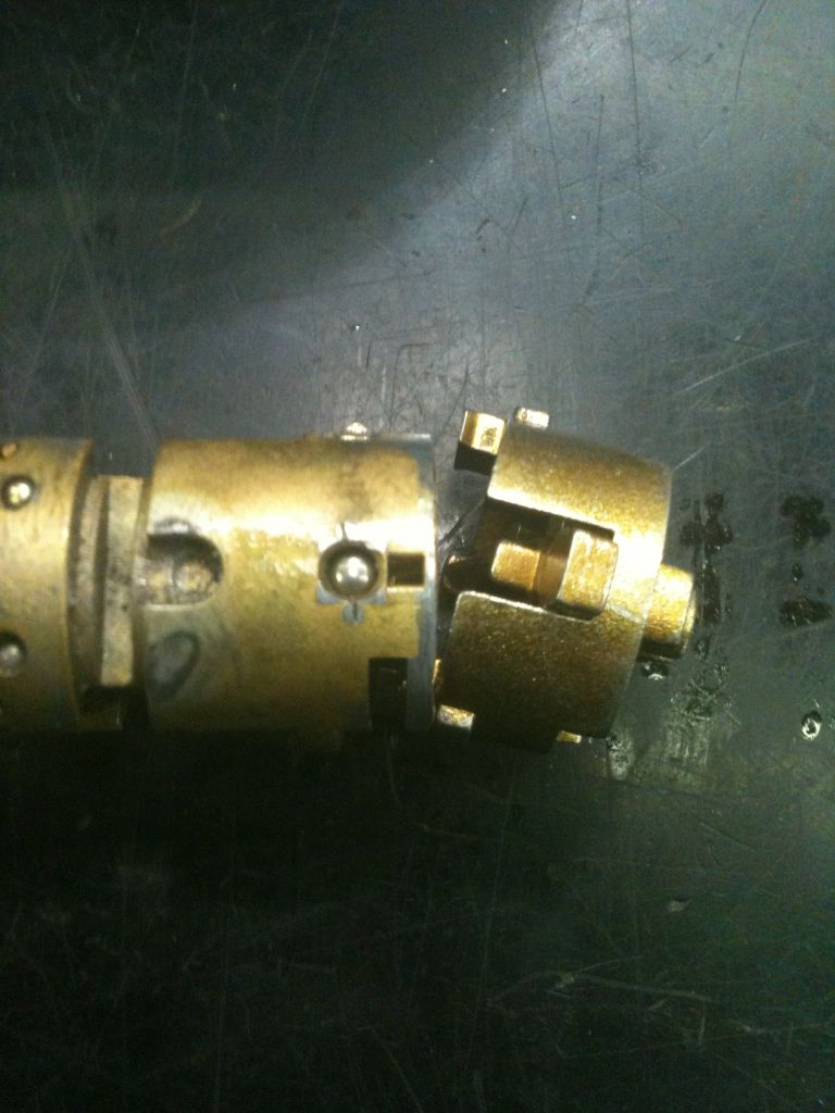
First to come out is the actuator, or at least one of the parts of it.
The lock core removed:
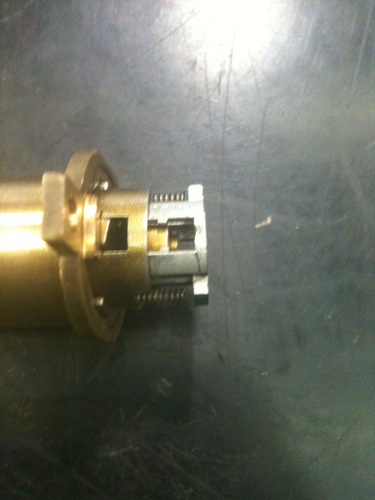
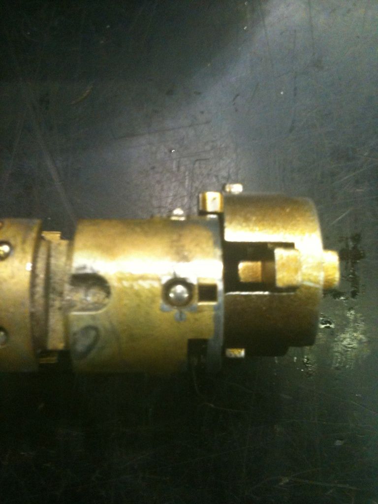
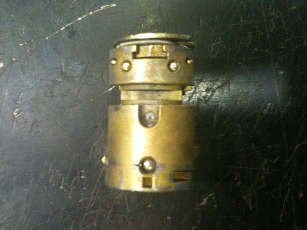
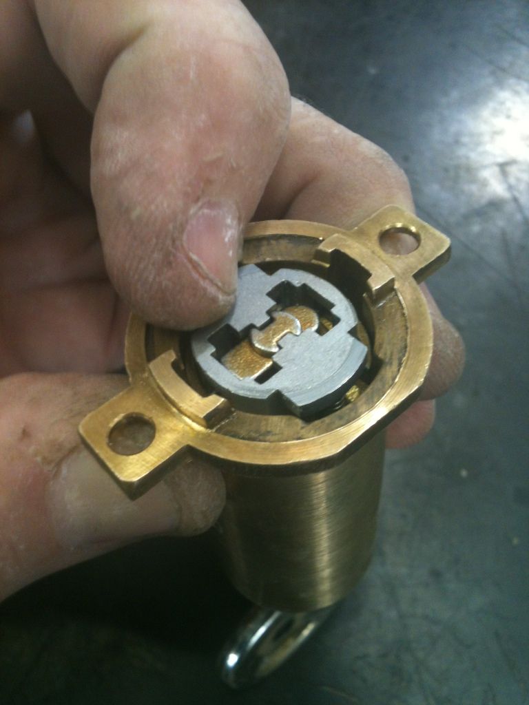
Inside the housing. Note that there is a large groove and a small groove going the length of the housing. Don’t try to put the lock together backwards. Inside the housing you can see grooves that go all the way around the housing. Tabs on the side of the lock core lock into these grooves to prevent punching the lock and prevent the lock core from moving in until the tabs are retracted or properly aligned.
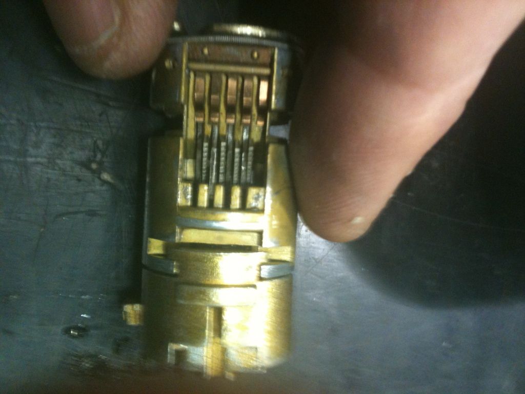
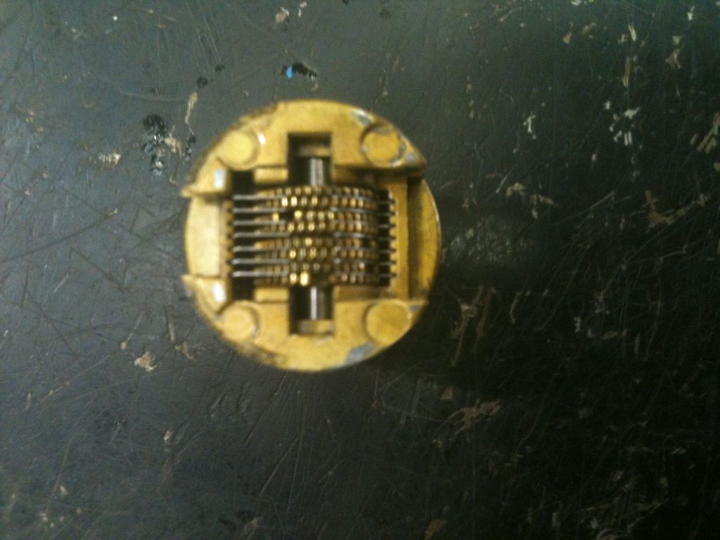
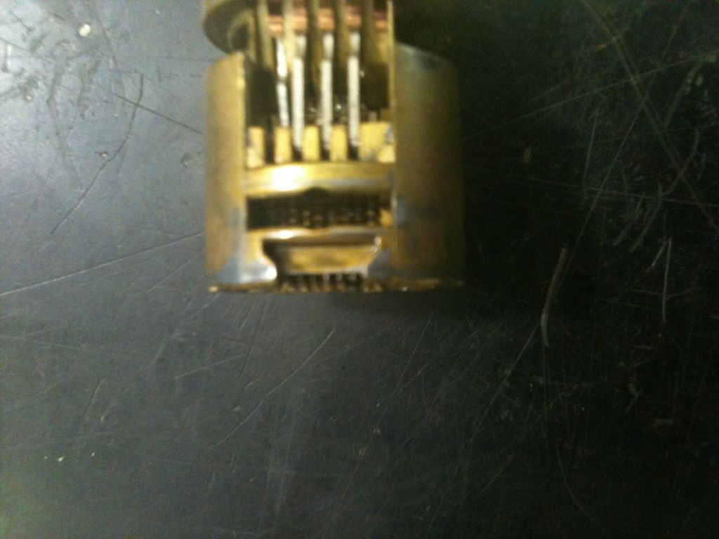
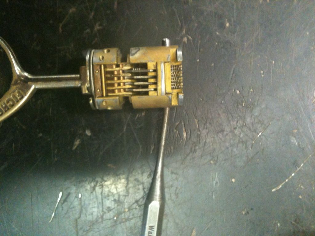
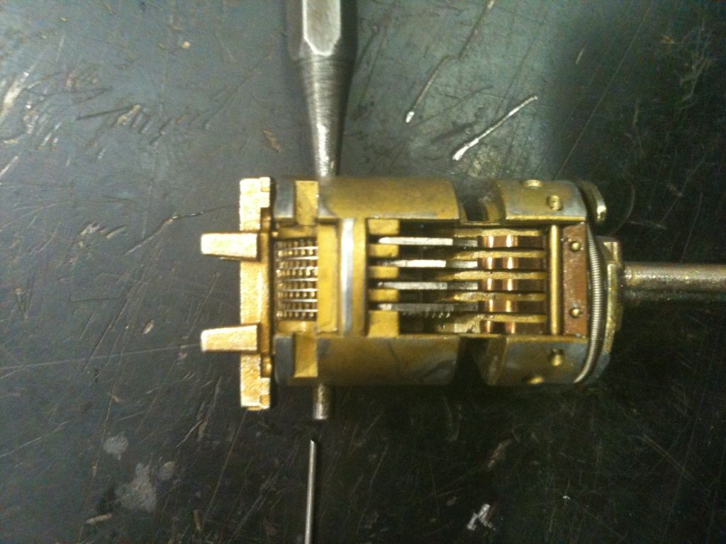
One side (with a large link). You can see the gears for half of the levers. The copper colored tabs at the top are part of the spring assembly. While connected at the top, the individual fingers provide springs for the levers. Five tabs, but each end tab only contacts one lever. There is a matching spring assembly on the other side.
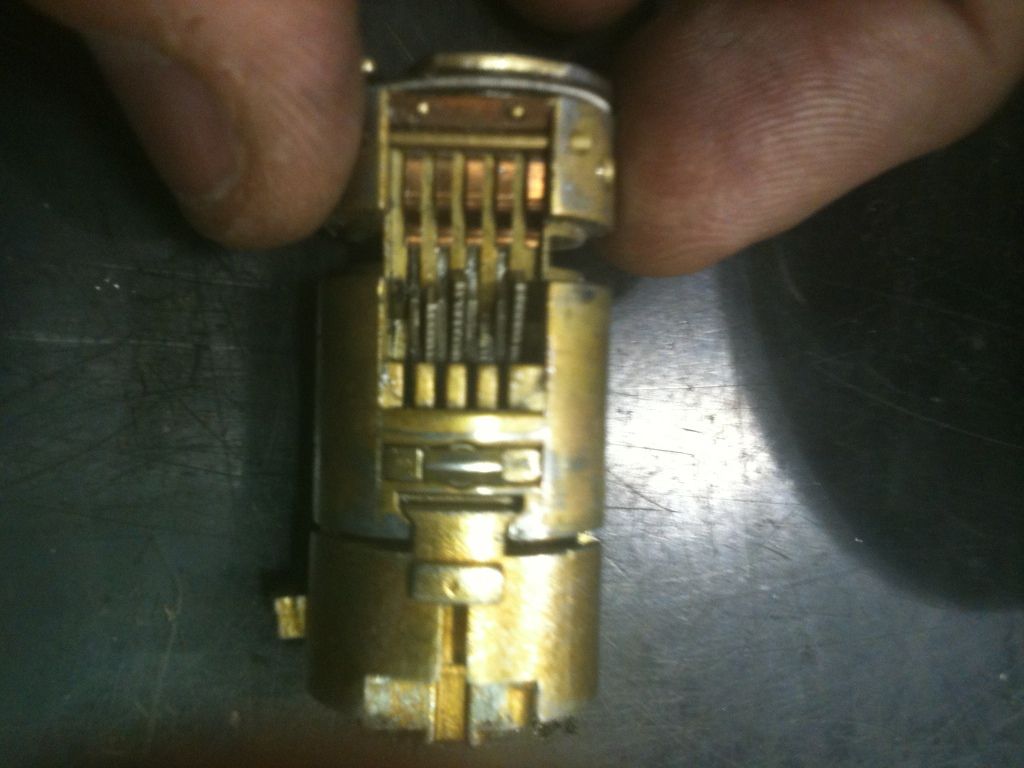
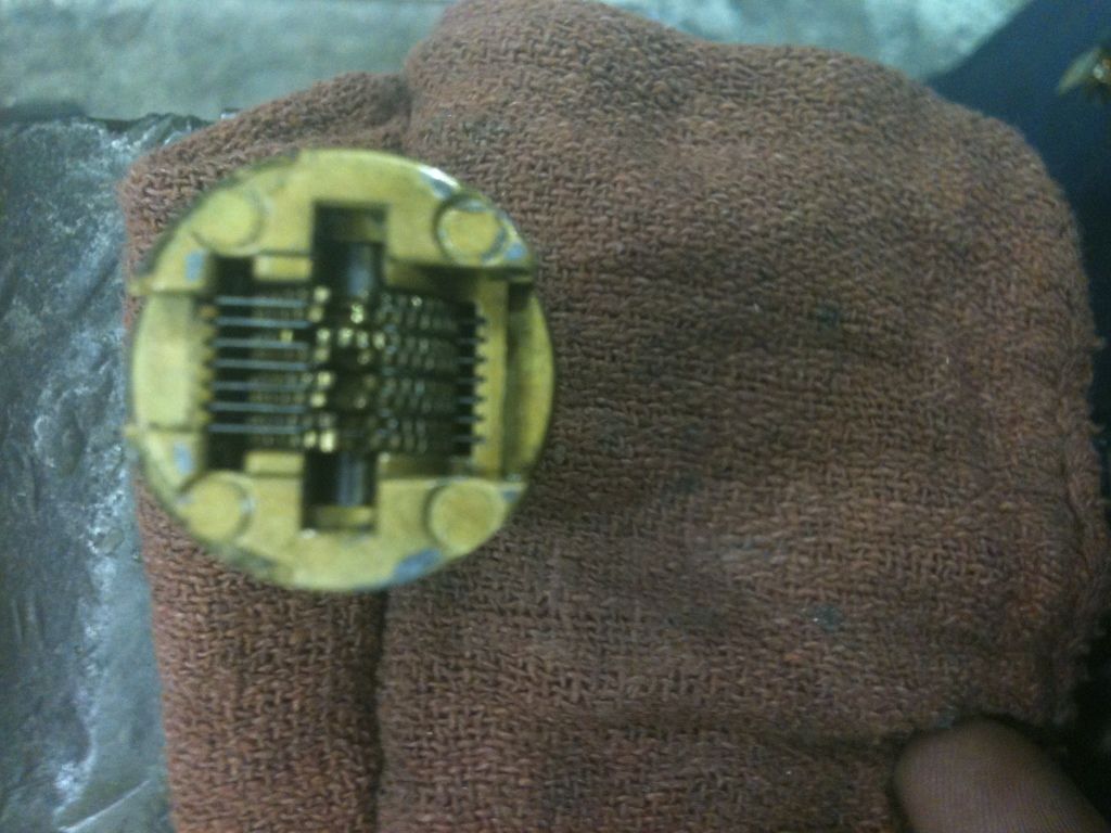
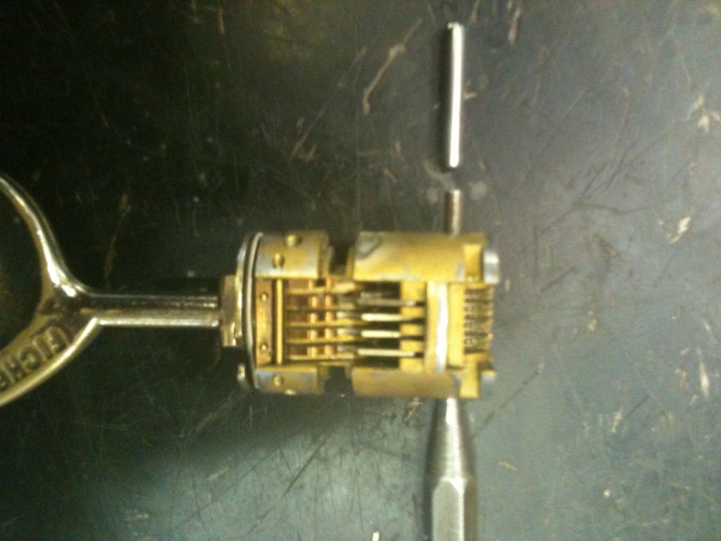
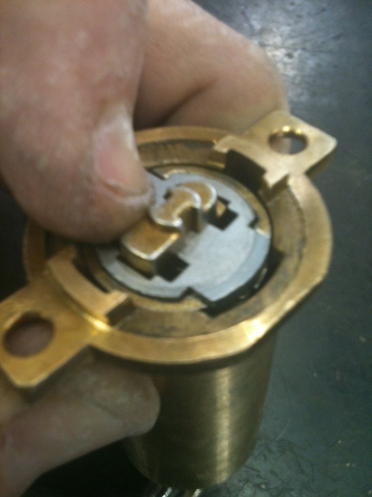
The other side (with a small link). Just above the link is a spring loaded tab that helps orient the core.
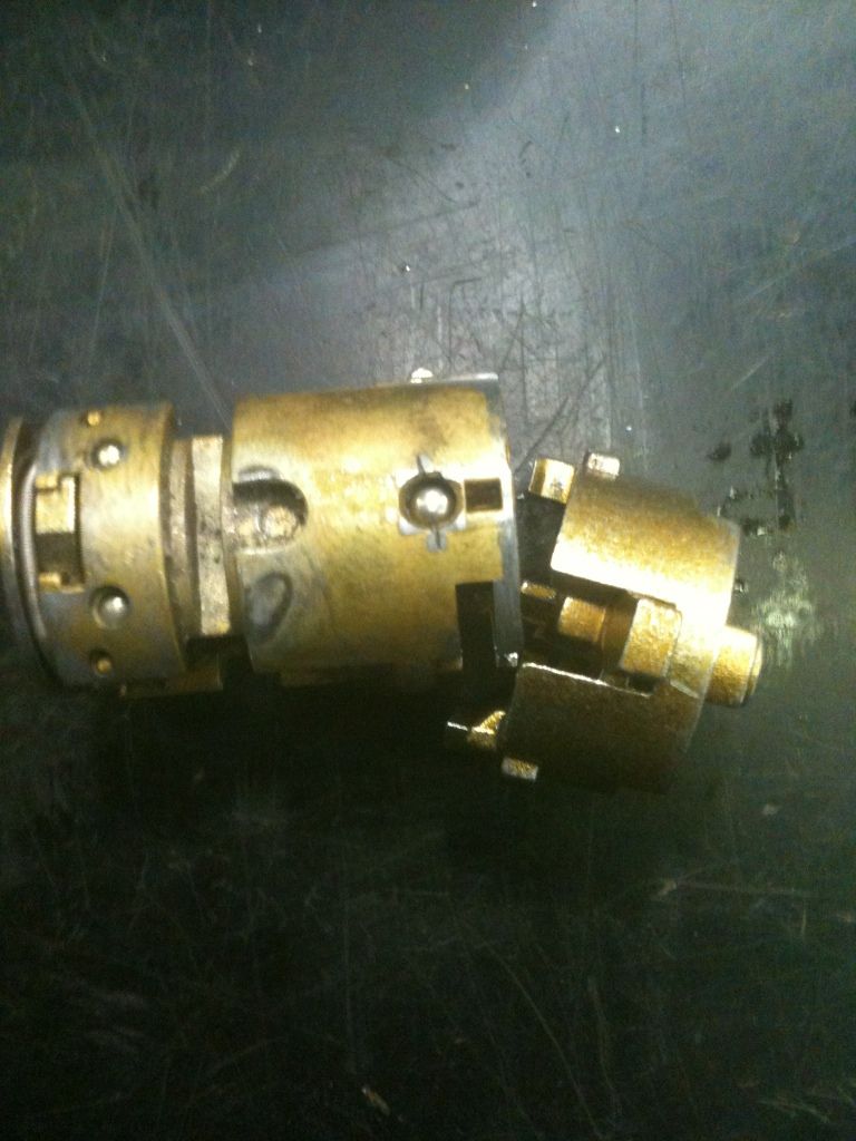
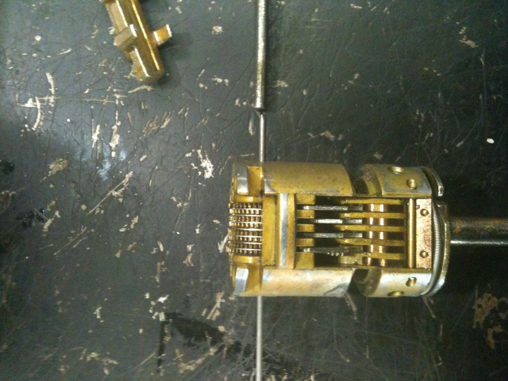
To disassemble the part that links onto the main lock core, slide towards the small link end until it clears the lock core.
Tip it outwards…
Then slide it downwards.
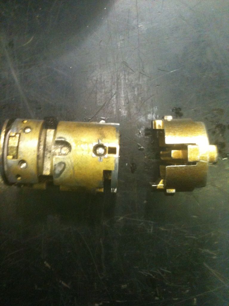
It is now separated.
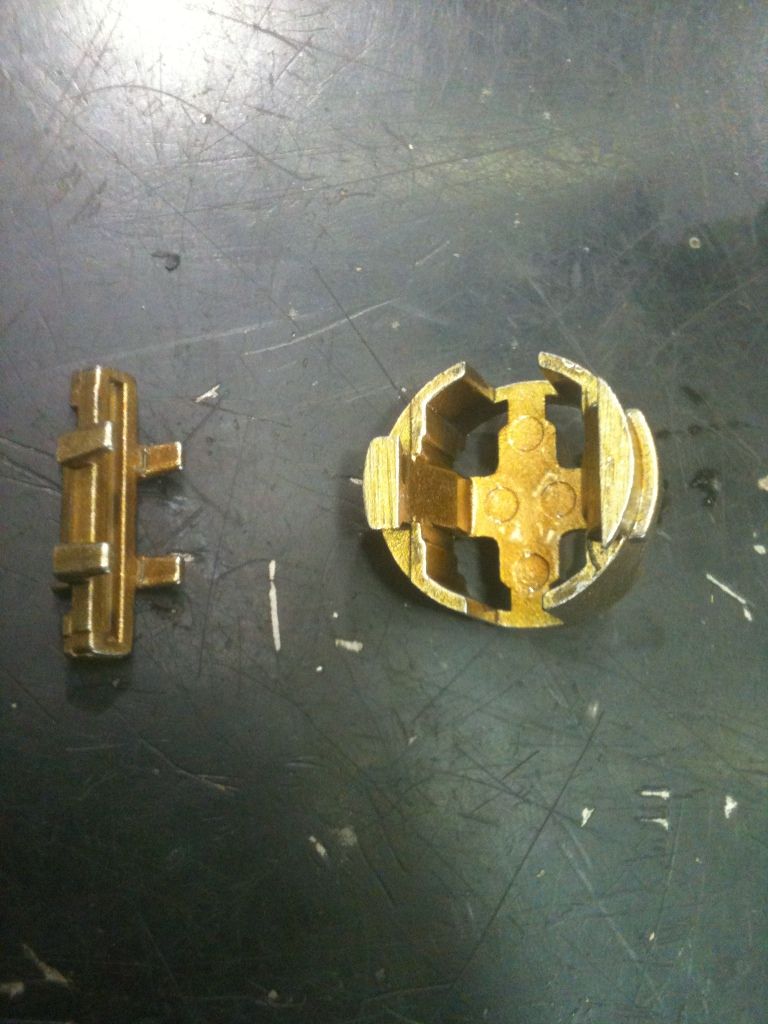
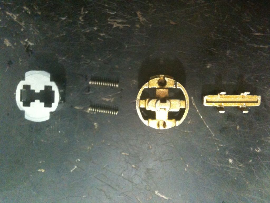
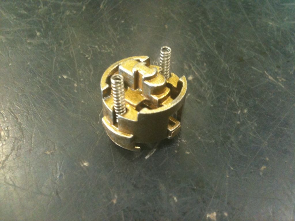
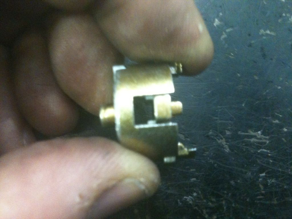
Am losing the game of trying to figure out names for these parts, so here is one view of the big brass part that we just removed and the part that the gates of the levers need to line up with for the core to move backwards. The ‘legs’ fit down into the other brass part, which faces away from the gates. More on the gates soon.
Another view of the two above parts. The springs fit into the holes on the brass part and into notches in the other metal part that appears to be pot metal. The pot metal part is furthest from the key.
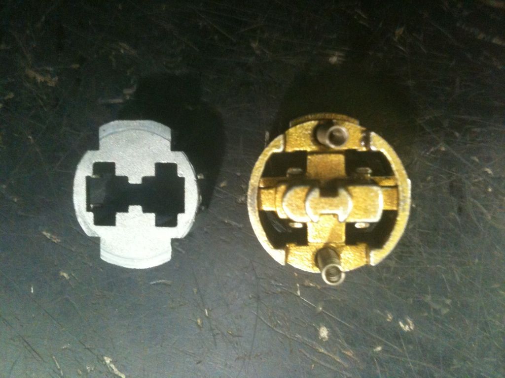
Partly assembled, you can see the part with the legs underneath the other brass part.
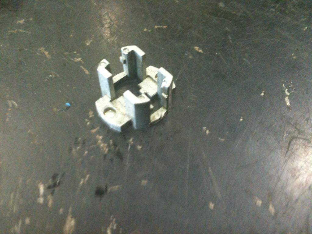
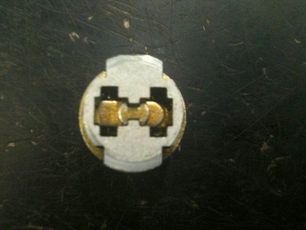
The other side of the pot metal part. At the top and bottom are the notches the springs fit into.
A better angle to see what the part looks like. It appears to be entirely cast.
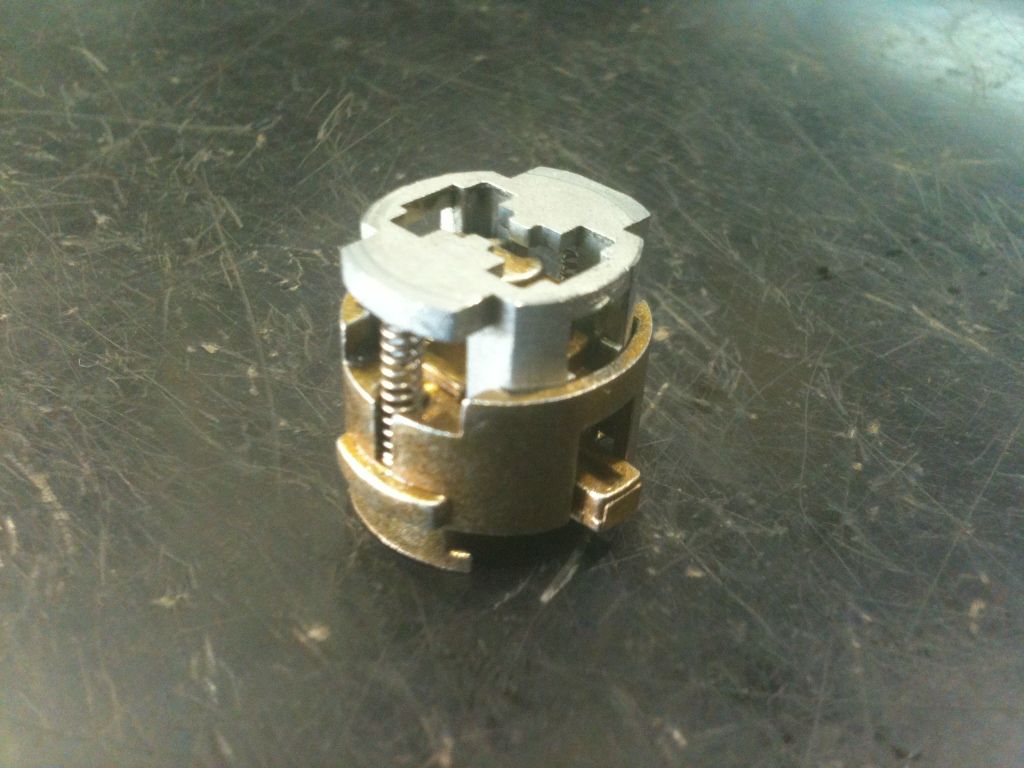
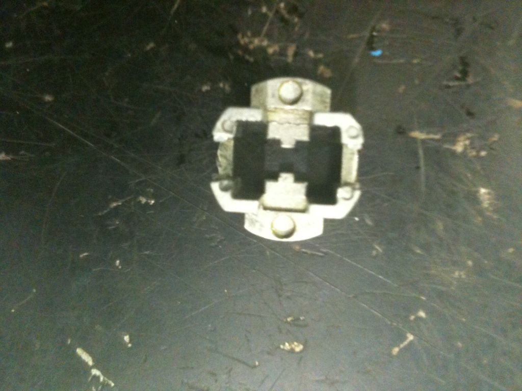
This is that assembly in the ‘locked’ position. To the right would be the rest of the lock core components and key, to the left would be the locking bolt mechanism.
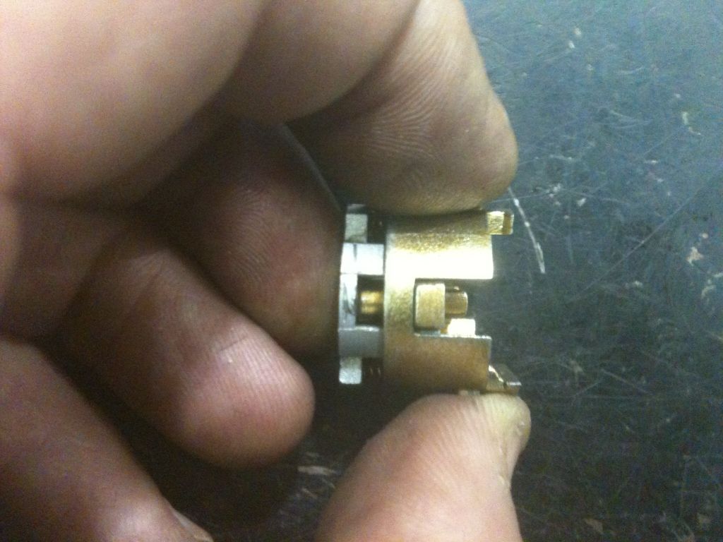
When ‘unlocked’ (correct key inserted), the core can be pressed inwards towards the locking bolt mechanism (compressing the springs). You can see the part that engages the bolt on the left now that the springs are compressed and the lock core moved inwards.
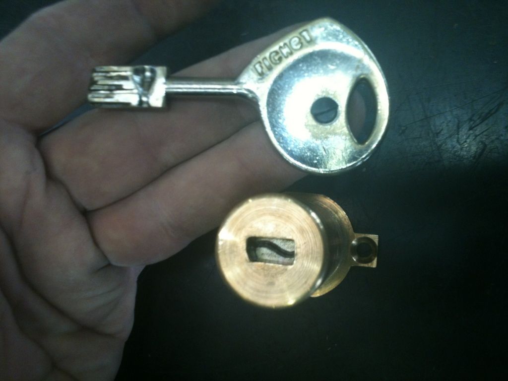
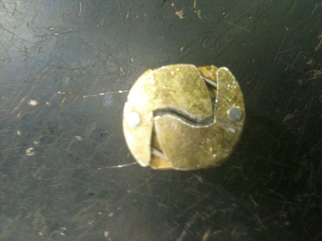
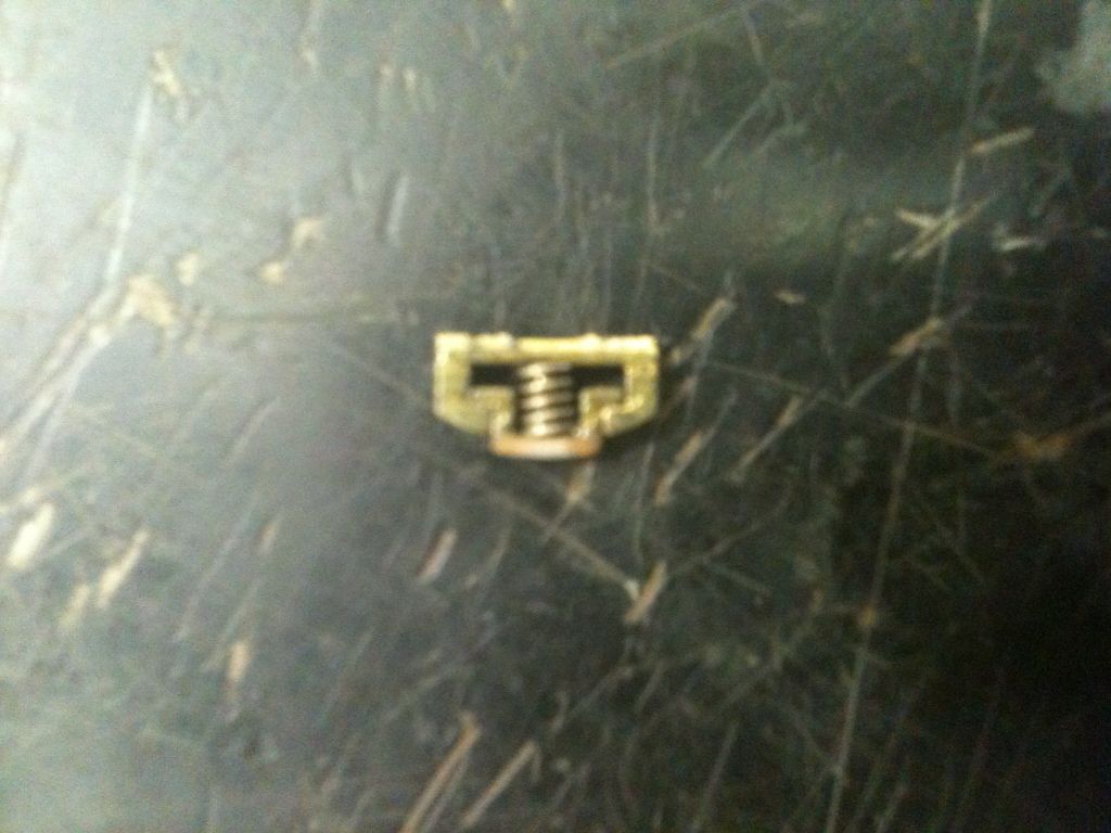
These are the shutters, which keep debris out of the lock and fit into grooves across the key.
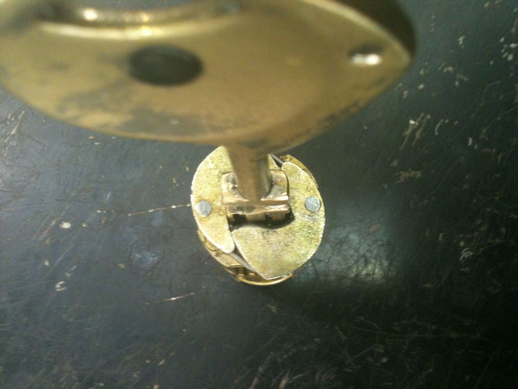
The key partly inserted. Note how the edges of the shutter are pushed outwards. They fit into one of the grooves in the lock housing, preventing the lock cylinder from moving inwards.
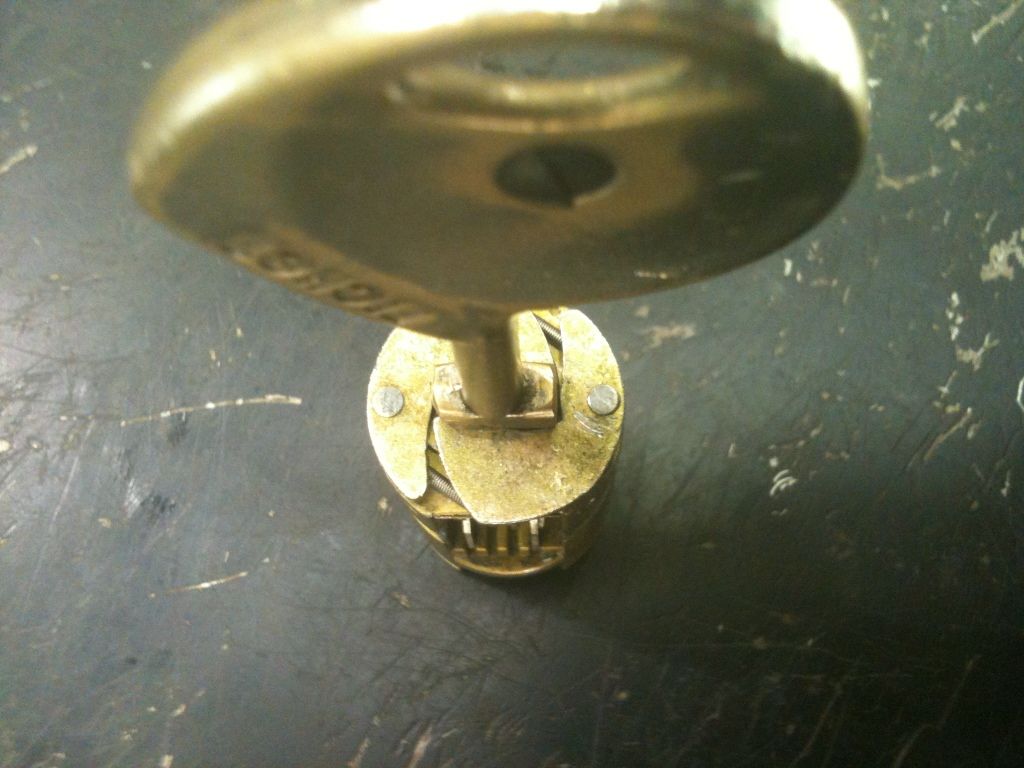
The key fully inserted. Parts of the shutters are now able to move inwards around the key. The outer part of the shutter now is out of the groove. This lock needs to be able to move inwards before it can be turned.
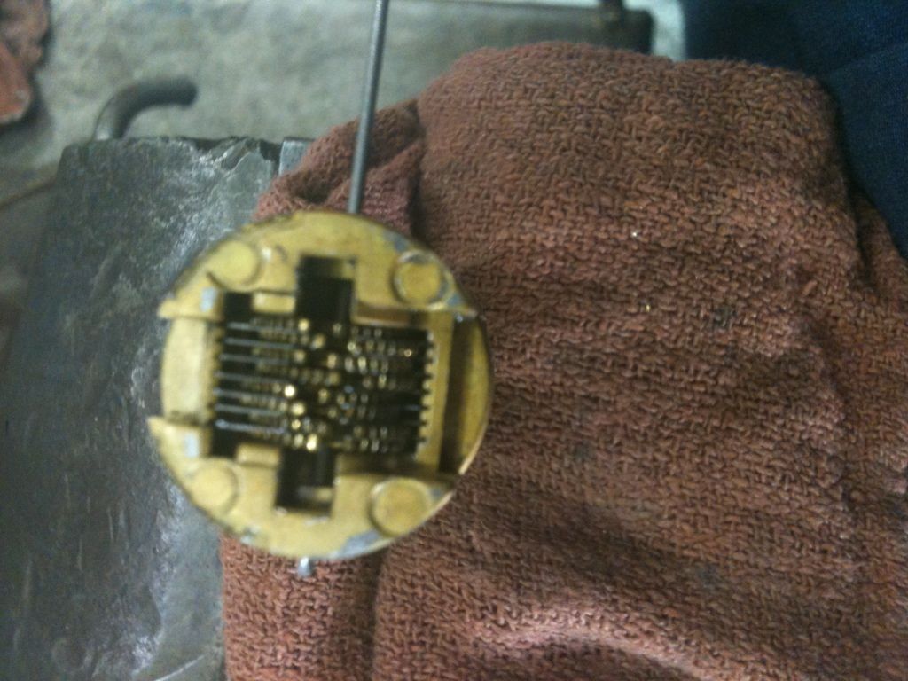
This is the part of the lock core that links to the above parts. You can see four gates, only the bottom one is lined up correctly. Without the key, the springs move the levers that you saw above, which are geared to these parts, causing the levers to self scramble.
I put the key into a vice, facing up. Then I slid the lock onto it fully. The gates should all line up. There is obvious wear on the key and parts, as the gates are not ‘perfectly’ aligned. But they would work if it were not for the third gear from the top. You can see that it is way out of alignment. Two gear teeth out, to be more accurate.
The key inserted, you can see the levers moved in various positions based on the key bits. Also, you can see that the shutter would clear the grooves in the lock housing.
Here the key is partly removed so you can see the difference in the levers above (you can now see many teeth on each of the four levers on this side. Also, the shutter is pushed out, into the groove if the core was in the lock body. That smooth (looking) band is the shutter spring. If the focus was better, you would see that it is not smooth at all.
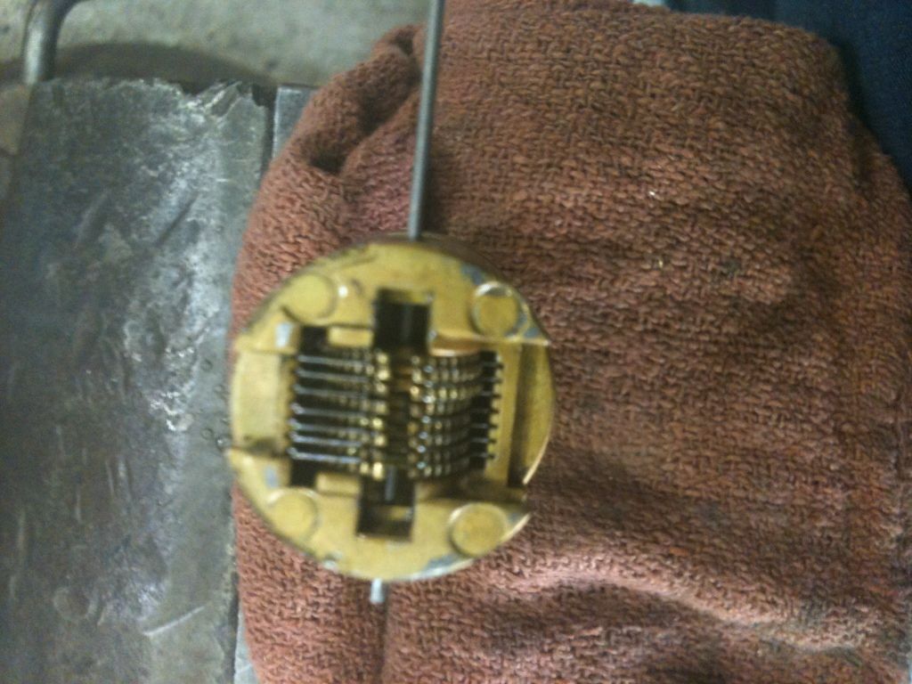
At the top of this shot are the shutters. The shiny part that looks like a ball bearing at the bottom is actually the pivot pin for the lower gears. The two shiny pins near the top center are the pivot pins for the four levers on each side of the keyway.
In the slot here, you can see the gear teeth. There is a part assembly that fits into here to line up the gear teeth better.
And here is that assembly. The larger outer part , the spring, and a omega-shaped part at the bottom that links with the top part.
At the top of the above part is this narrow bar that fits into the gear teeth.
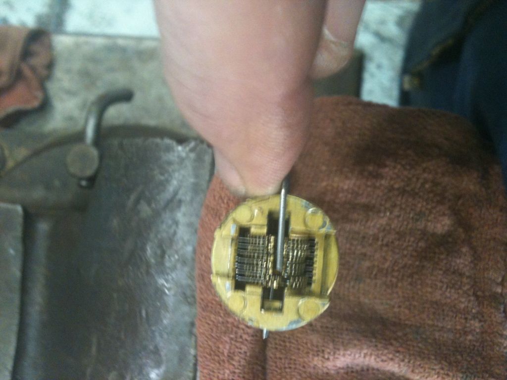
Use a punch to drive out the large pivot pin (with the key installed). This can easily be pushed out - no need for hammers.
Since the punch is of narrower than the pivot pin, hope to be able to adjust the out-of-position gear by sliding it upwards, unmeshing the gear teeth and rotating it.
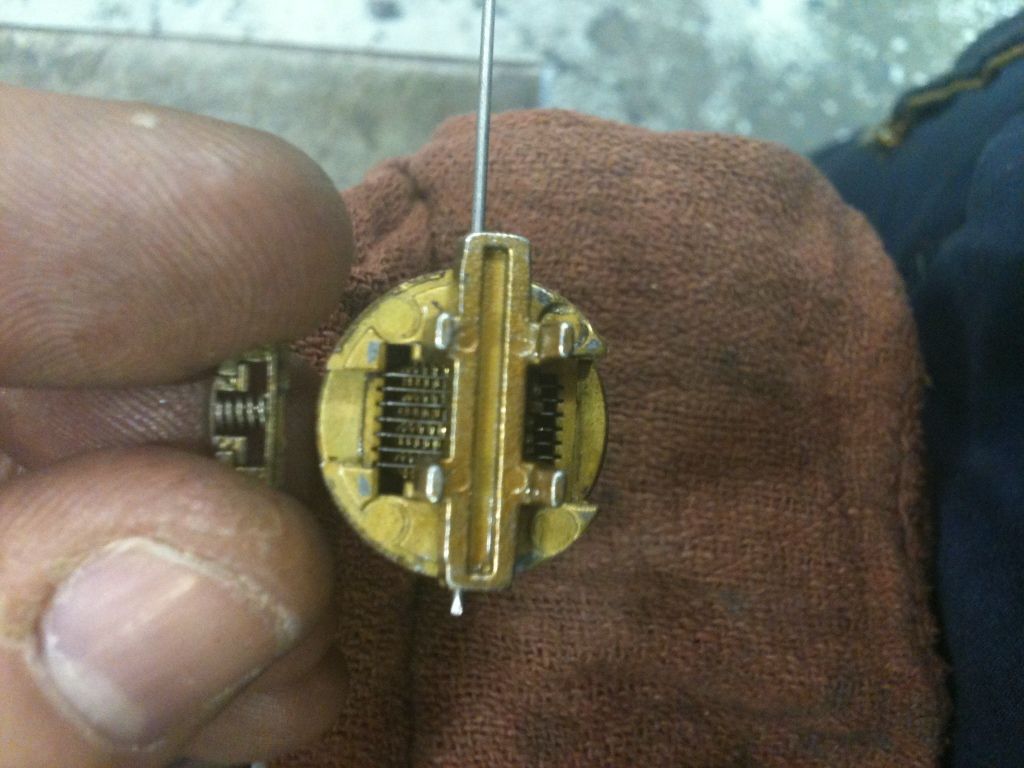
Unfortunately, the lock decided to dash my hopes. Used a music wire tool (specifically, a tension wrench made for a Vachette AXI Home lock) to push out the punch, giving a bit more free room to adjust the gears. Don’t want to take this lock completely apart at work if it can be helped. Parts would get lost, never to be found again.
Without the fatter pivot pin (or punch) in place, the gears move freely (almost).
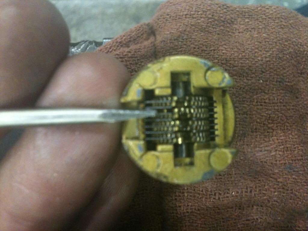
Use another music wire tool (tubular lock poker pick ) to align the gates.
Hey! Alright, we are on our way! Also note that the gear ‘tooth’ on each side of the gate is larger and wider. That could come in handy picking!
Put in the part that is supposed to fit into the gates in place (without the rest of the stuff) to help hold the gates in place. Then put in that assembly in place into the slot to lock the gear teeth in place.
Tried putting in the pivot pin directly, but the gears are not aligned enough. So put the punch in place.
Put in the pivot pin.
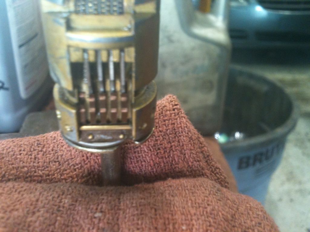
Reassemble in reverse of the above steps. Here the key is partly in. The lock core can not move inwards.
Key pushed in, the core pushed inwards. The bolt mechanism would now be engaged…
And turned! This lock is now fixed!
Gordon
Won two of these from the same lockset (inner and outer) on eBay a while back. The inner lock worked great, but the outer one (this one) did not work. Finally had some time today at work to disassemble it to find out why it did not work.
First, had to drill out the two hardened steel pins they used on the outer lock housing so we (you and I) could take a look inside. Since they were hardened steel pins, they laughed at my drill bits.
Now you can push the lock cylinder out of the housing:
Remove the key, then use a thin screwdriver or straight tool to push the lock cylinder out.
First to come out is the actuator, or at least one of the parts of it.
The lock core removed:
Inside the housing. Note that there is a large groove and a small groove going the length of the housing. Don’t try to put the lock together backwards.
One side (with a large link). You can see the gears for half of the levers. The copper colored tabs at the top are part of the spring assembly. While connected at the top, the individual fingers provide springs for the levers. Five tabs, but each end tab only contacts one lever. There is a matching spring assembly on the other side.
The other side (with a small link). Just above the link is a spring loaded tab that helps orient the core.
To disassemble the part that links onto the main lock core, slide towards the small link end until it clears the lock core.
Tip it outwards…
Then slide it downwards.
It is now separated.
Am losing the game of trying to figure out names for these parts, so here is one view of the big brass part that we just removed and the part that the gates of the levers need to line up with for the core to move backwards. The ‘legs’ fit down into the other brass part, which faces away from the gates. More on the gates soon.
Another view of the two above parts. The springs fit into the holes on the brass part and into notches in the other metal part that appears to be pot metal. The pot metal part is furthest from the key.
Partly assembled, you can see the part with the legs underneath the other brass part.
The other side of the pot metal part. At the top and bottom are the notches the springs fit into.
A better angle to see what the part looks like. It appears to be entirely cast.
This is that assembly in the ‘locked’ position. To the right would be the rest of the lock core components and key, to the left would be the locking bolt mechanism.
When ‘unlocked’ (correct key inserted), the core can be pressed inwards towards the locking bolt mechanism (compressing the springs). You can see the part that engages the bolt on the left now that the springs are compressed and the lock core moved inwards.
These are the shutters, which keep debris out of the lock and fit into grooves across the key.
The key partly inserted. Note how the edges of the shutter are pushed outwards. They fit into one of the grooves in the lock housing, preventing the lock cylinder from moving inwards.
The key fully inserted. Parts of the shutters are now able to move inwards around the key. The outer part of the shutter now is out of the groove. This lock needs to be able to move inwards before it can be turned.
This is the part of the lock core that links to the above parts. You can see four gates, only the bottom one is lined up correctly. Without the key, the springs move the levers that you saw above, which are geared to these parts, causing the levers to self scramble.
I put the key into a vice, facing up. Then I slid the lock onto it fully. The gates should all line up. There is obvious wear on the key and parts, as the gates are not ‘perfectly’ aligned. But they would work if it were not for the third gear from the top. You can see that it is way out of alignment. Two gear teeth out, to be more accurate.
The key inserted, you can see the levers moved in various positions based on the key bits. Also, you can see that the shutter would clear the grooves in the lock housing.
Here the key is partly removed so you can see the difference in the levers above (you can now see many teeth on each of the four levers on this side. Also, the shutter is pushed out, into the groove if the core was in the lock body. That smooth (looking) band is the shutter spring. If the focus was better, you would see that it is not smooth at all.
At the top of this shot are the shutters. The shiny part that looks like a ball bearing at the bottom is actually the pivot pin for the lower gears. The two shiny pins near the top center are the pivot pins for the four levers on each side of the keyway.
In the slot here, you can see the gear teeth. There is a part assembly that fits into here to line up the gear teeth better.
And here is that assembly. The larger outer part , the spring, and a omega-shaped part at the bottom that links with the top part.
At the top of the above part is this narrow bar that fits into the gear teeth.
Use a punch to drive out the large pivot pin (with the key installed). This can easily be pushed out - no need for hammers.
Since the punch is of narrower than the pivot pin, hope to be able to adjust the out-of-position gear by sliding it upwards, unmeshing the gear teeth and rotating it.
Unfortunately, the lock decided to dash my hopes.
Without the fatter pivot pin (or punch) in place, the gears move freely (almost).
Use another music wire tool (tubular lock poker pick
Hey! Alright, we are on our way! Also note that the gear ‘tooth’ on each side of the gate is larger and wider. That could come in handy picking!
Put in the part that is supposed to fit into the gates in place (without the rest of the stuff) to help hold the gates in place. Then put in that assembly in place into the slot to lock the gear teeth in place.
Tried putting in the pivot pin directly, but the gears are not aligned enough. So put the punch in place.
Put in the pivot pin.
Reassemble in reverse of the above steps. Here the key is partly in. The lock core can not move inwards.
Key pushed in, the core pushed inwards. The bolt mechanism would now be engaged…
And turned! This lock is now fixed!
Gordon
Just when you think you've learned it all, that is when you find you haven't learned anything yet.