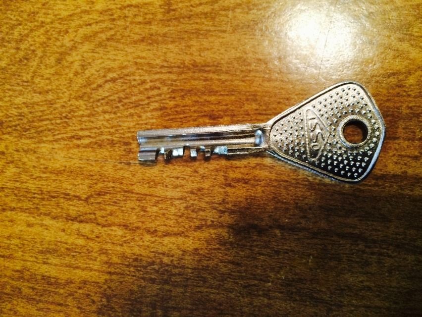
Teardown of and key made for Abloy 656
Posted the key a while ago, but never got around to a post on the teardown of this lock. Oldfast - grab your tissues. There are gut shots. 
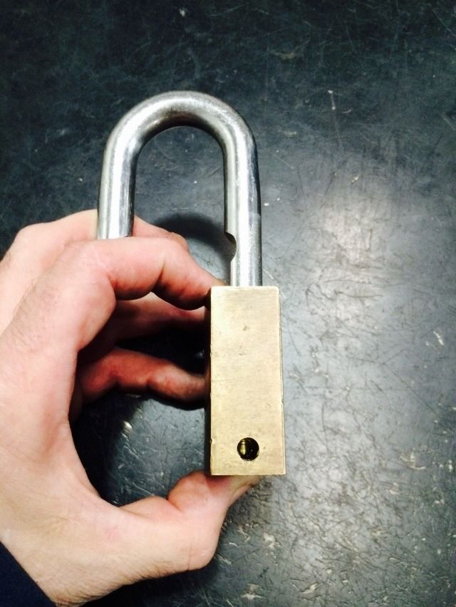
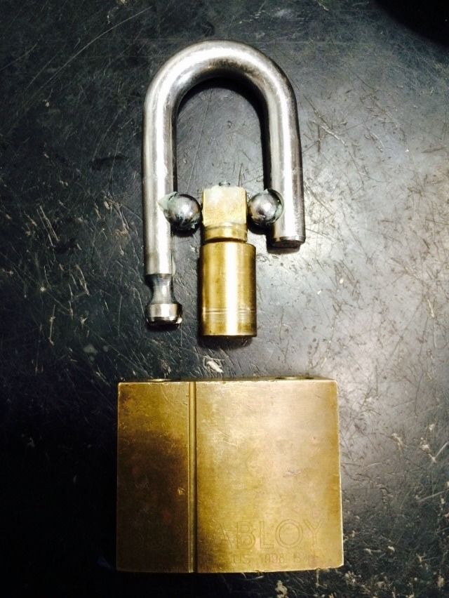
Again, this is the Abloy 656
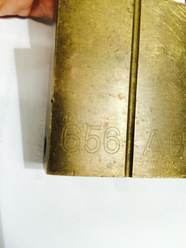
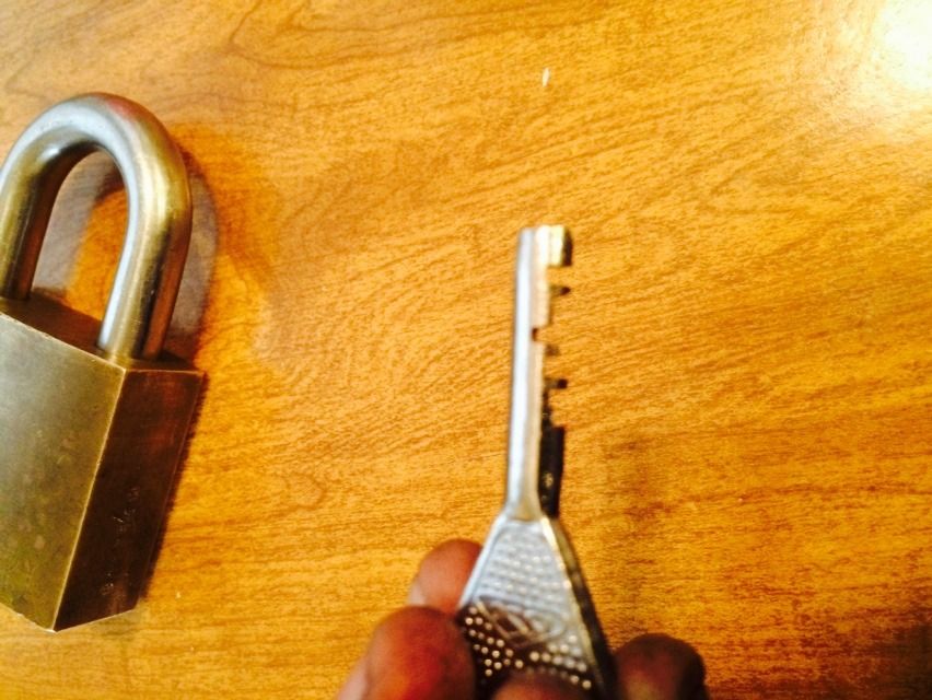
This is a massive lock.
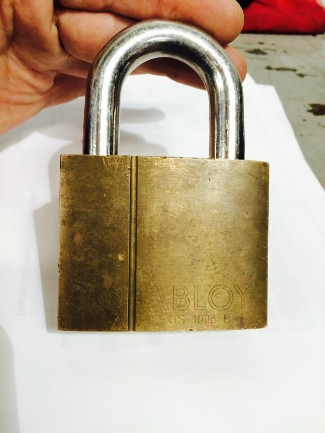
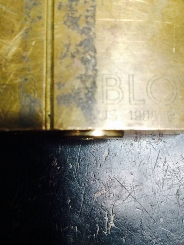
Abloy Profile cylinder.
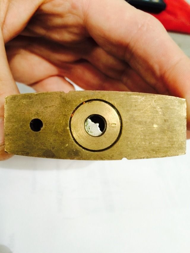
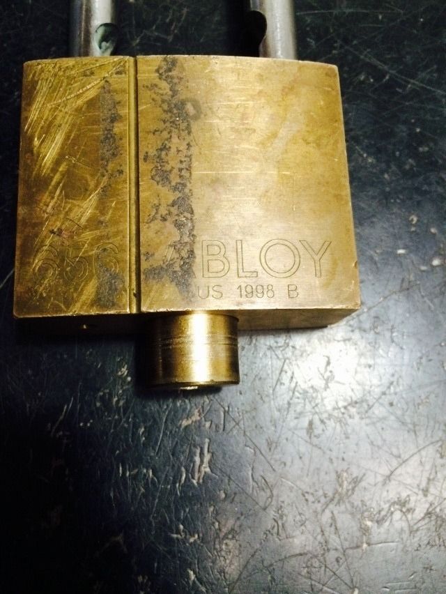
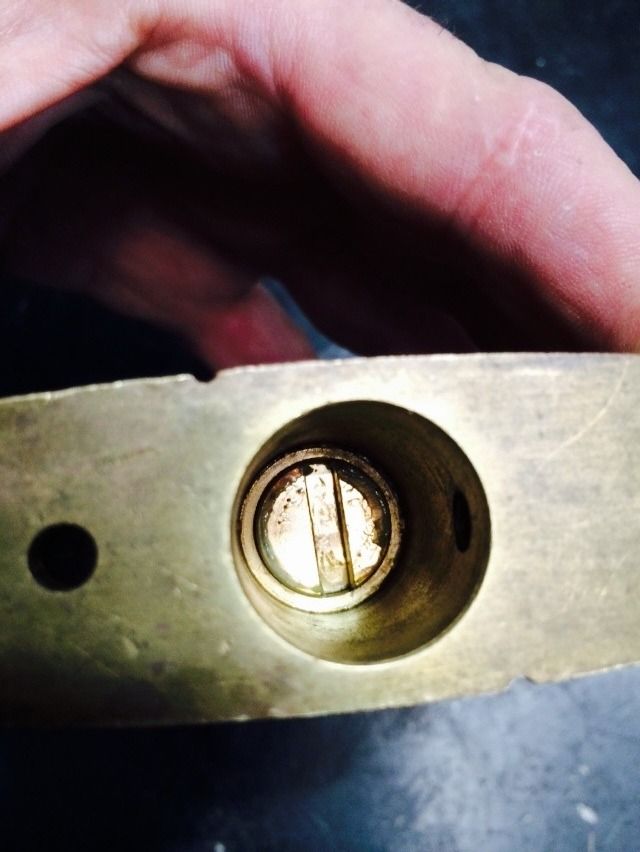
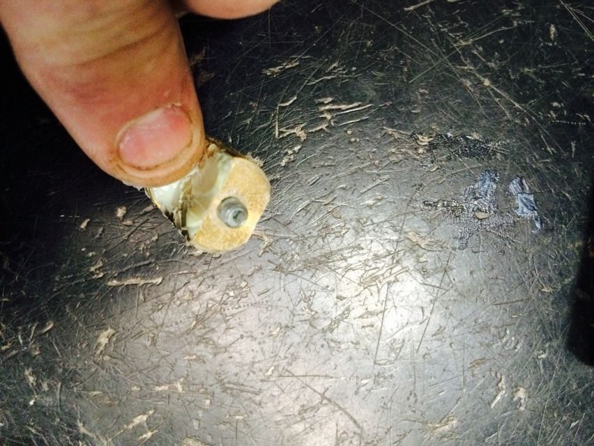
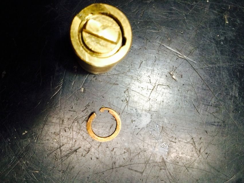
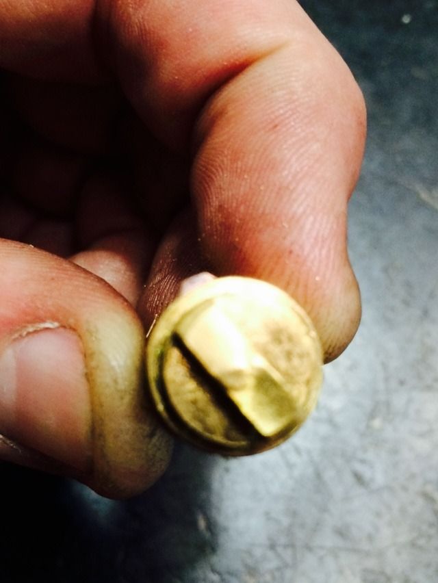
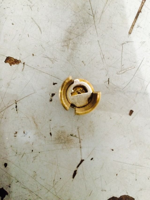
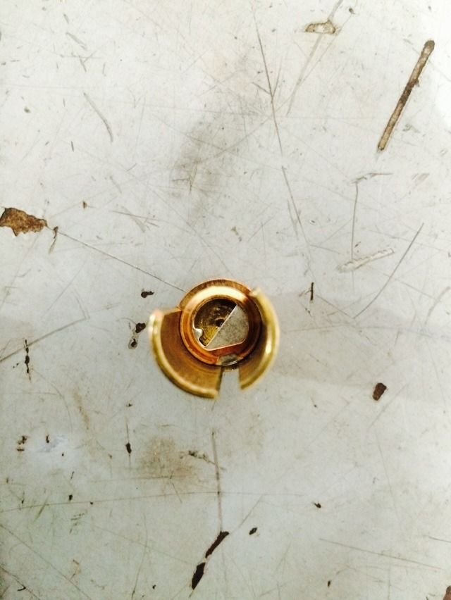
The core assembly is held in by a retainer screw inside this hole.
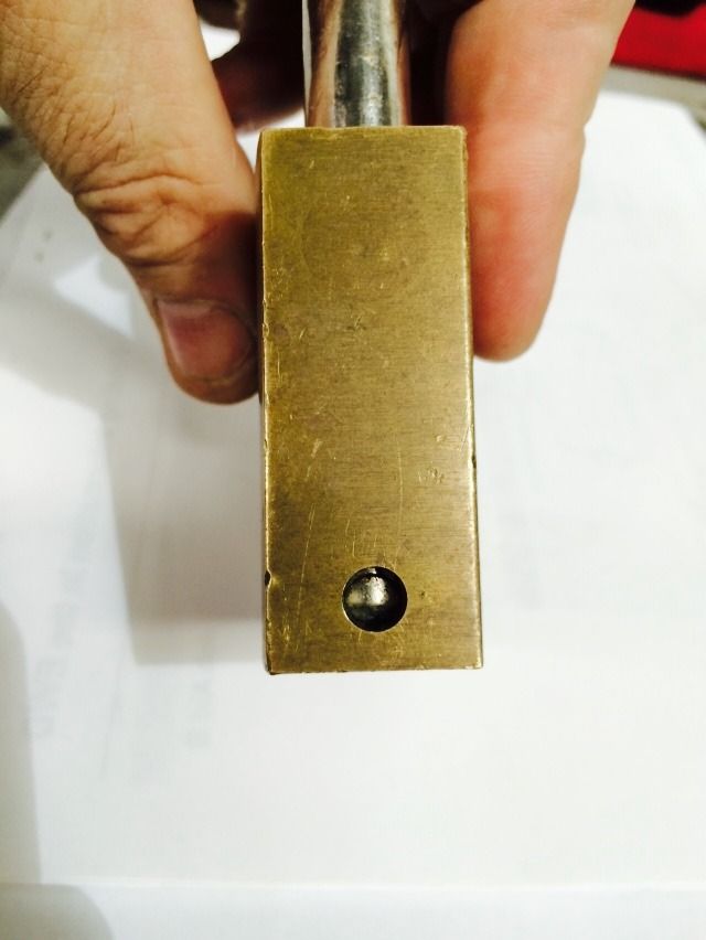
The screw is reached by having the lock unlocked.
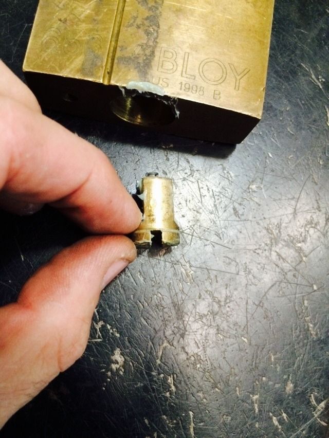
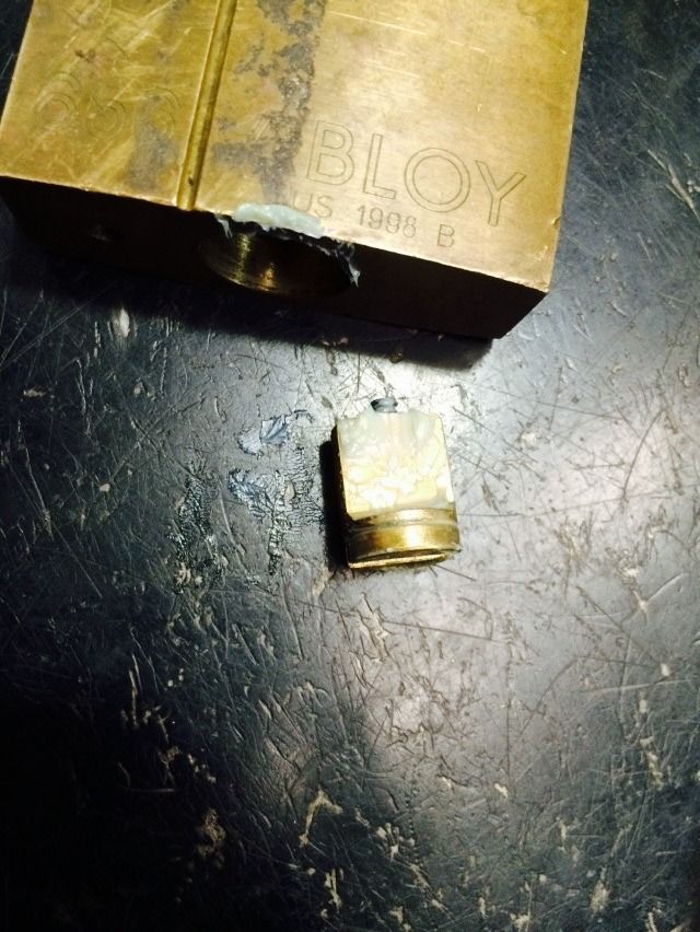
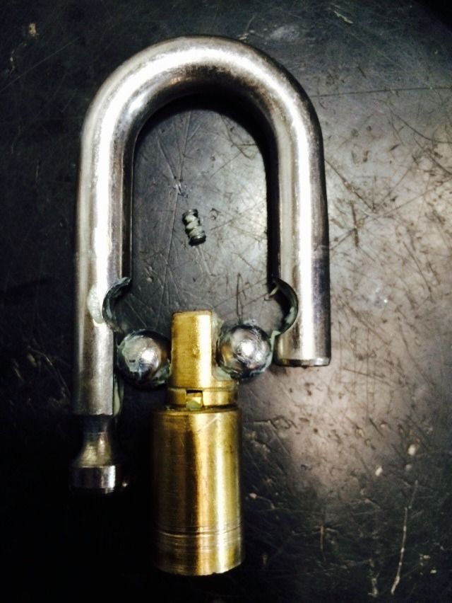
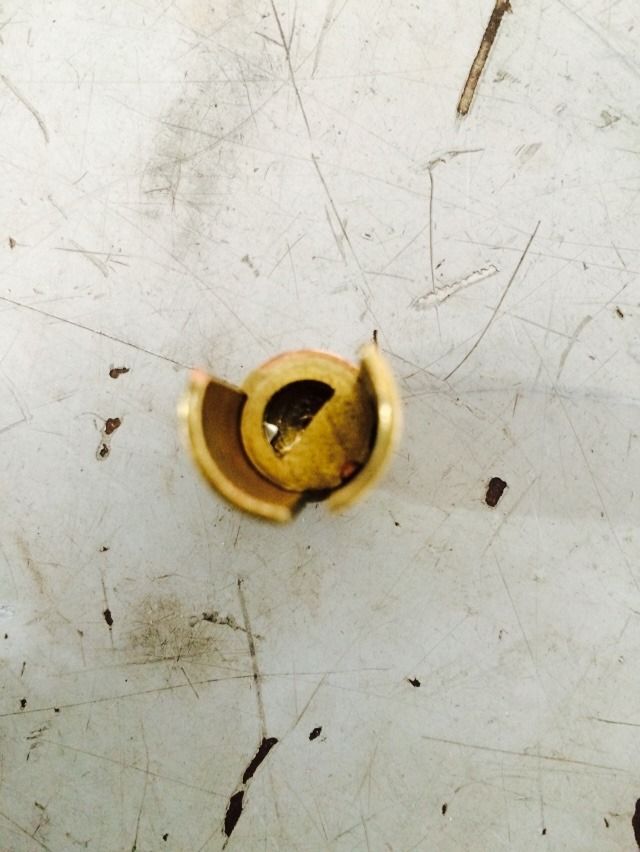
When the retainer screw is backed out sufficiently, the core will pop out a small distance due to a spring.
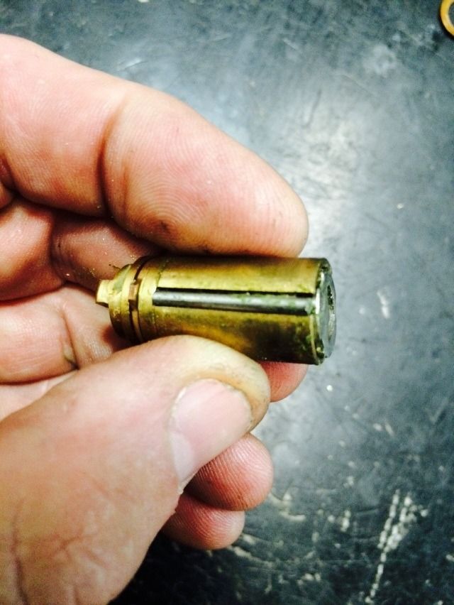
Then you simply pull out the core. It is not a retainer ring like most Abloy padlocks.
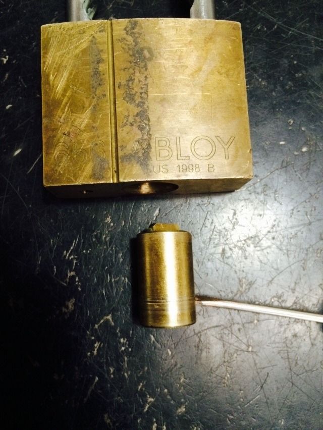
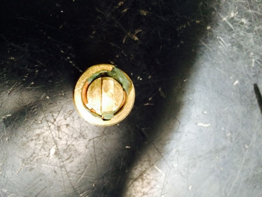
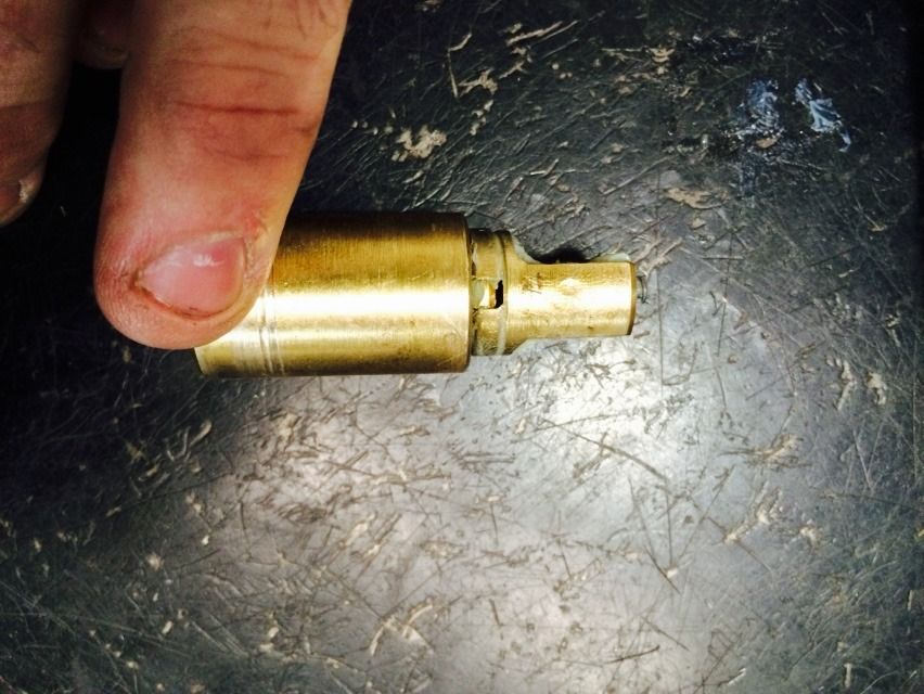
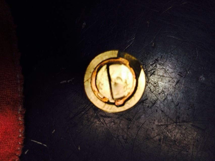
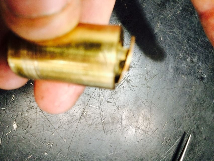
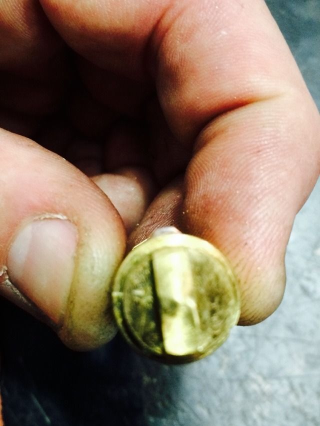
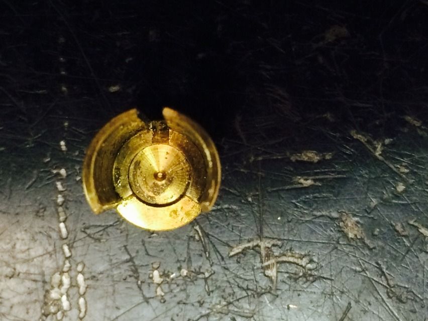
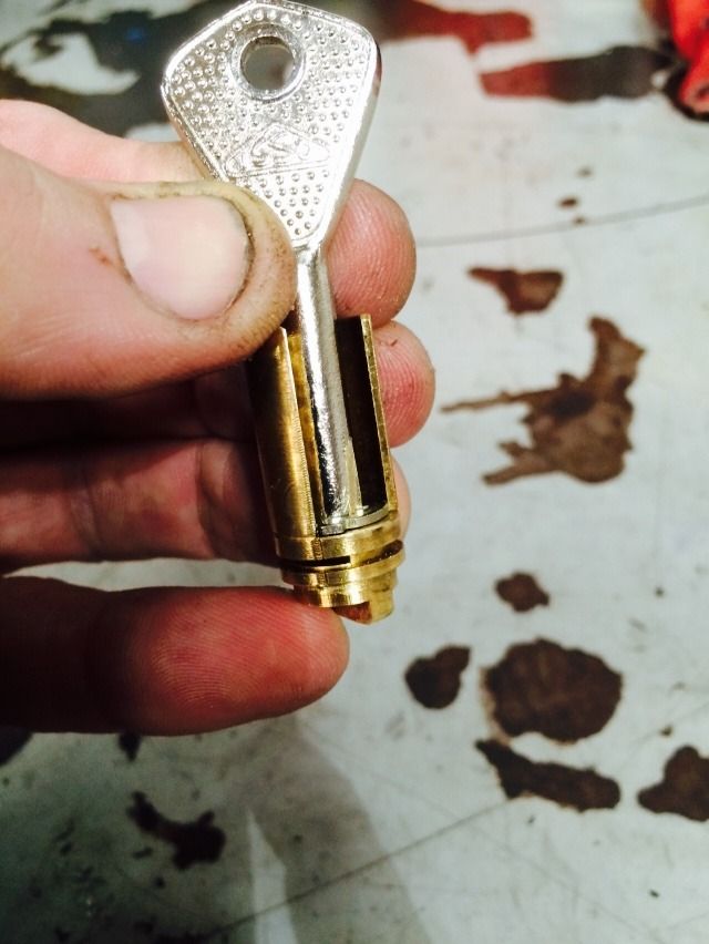
The tailpiece of the core is simple.
Back to the core shortly. For now, let's finish disassembling the padlock. Looking into the lock body, you can see the cam.
Turn the lock so the shackle is up, and tap it on your hand a couple times, and the cam will fall out into your hand.
The cam turned 90 degrees, to the locked position.
This is the top end of the cam, that faces the top of the lock. This spring is what pushes the core/carrier assembly out that little bit.
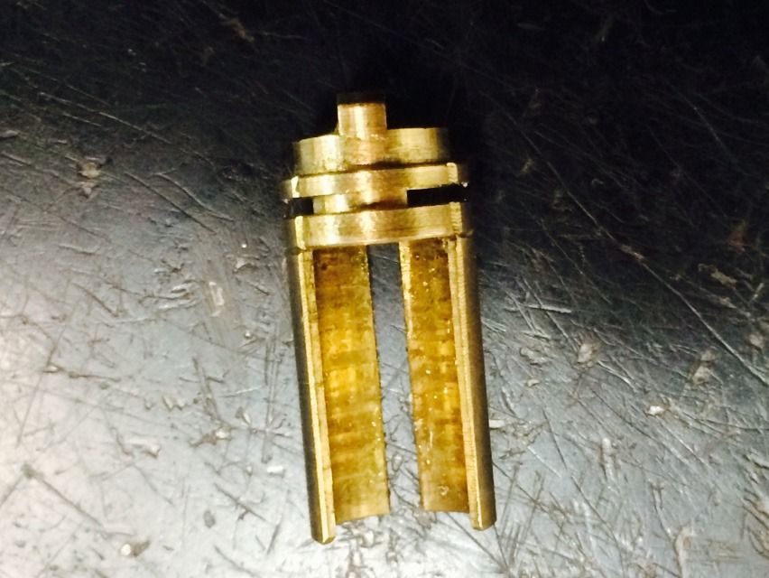
The tailpiece of the core and the cam fit together like so:
Here are the internals of the lock in the unlocked position.
And locked. (Very simple mechanism).
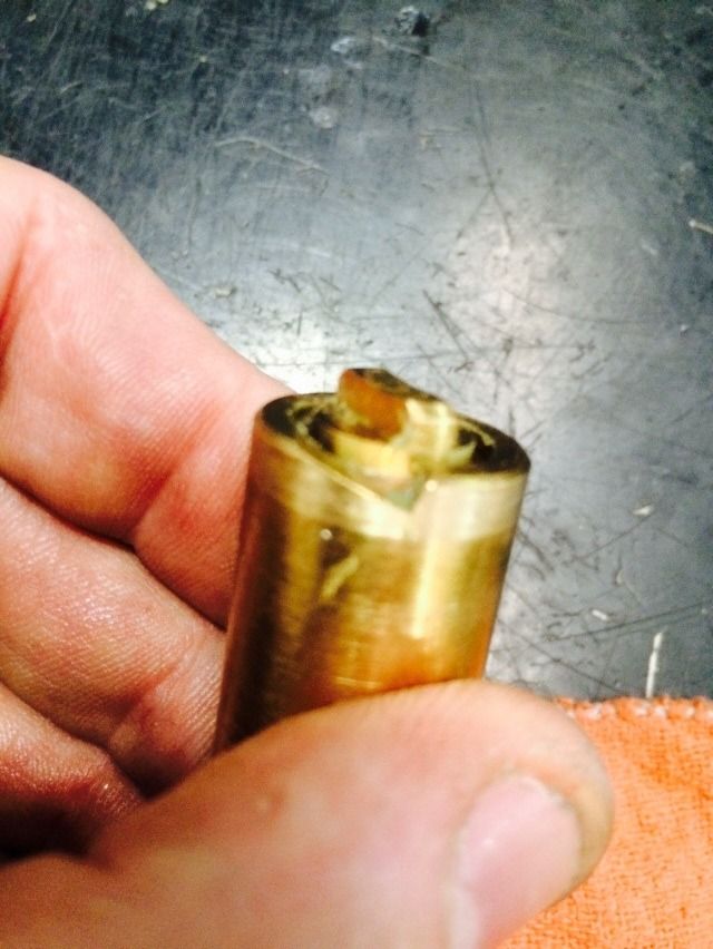
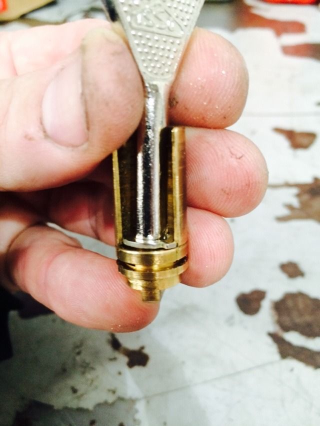
OK, time for taking the core assembly apart. Looking at the end of the carrier, there is a clip.
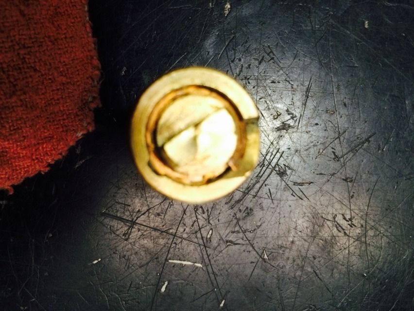
And a ramp (when viewed from the side):
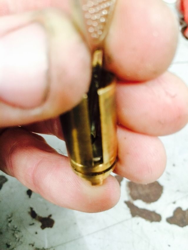
Rotate the clip until it starts to go up the ramp. You will need to help it go up the ramp at first using a 90 degree pick.
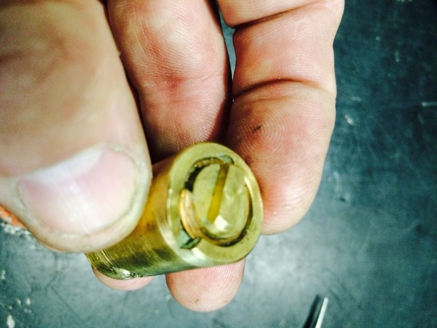
And keep rotating the clip until it has been removed.
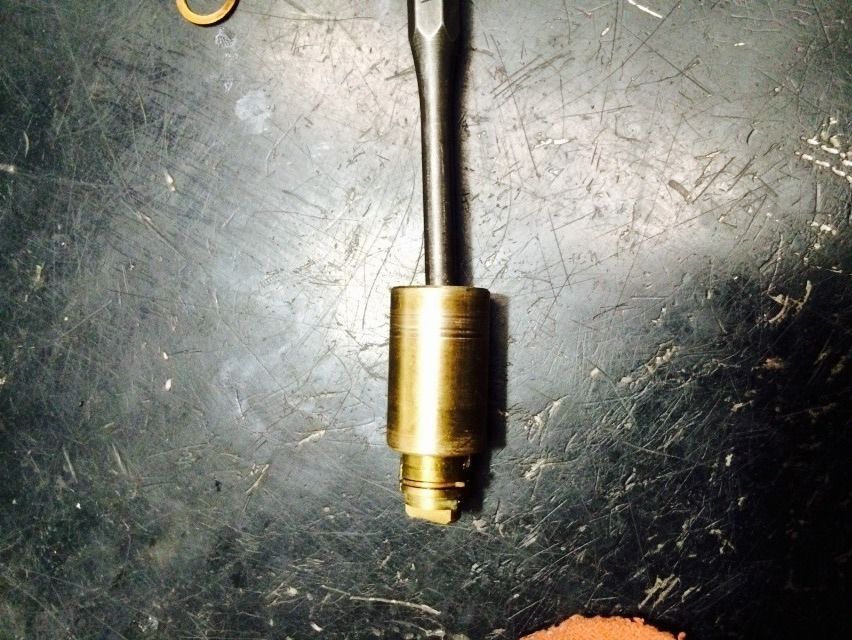
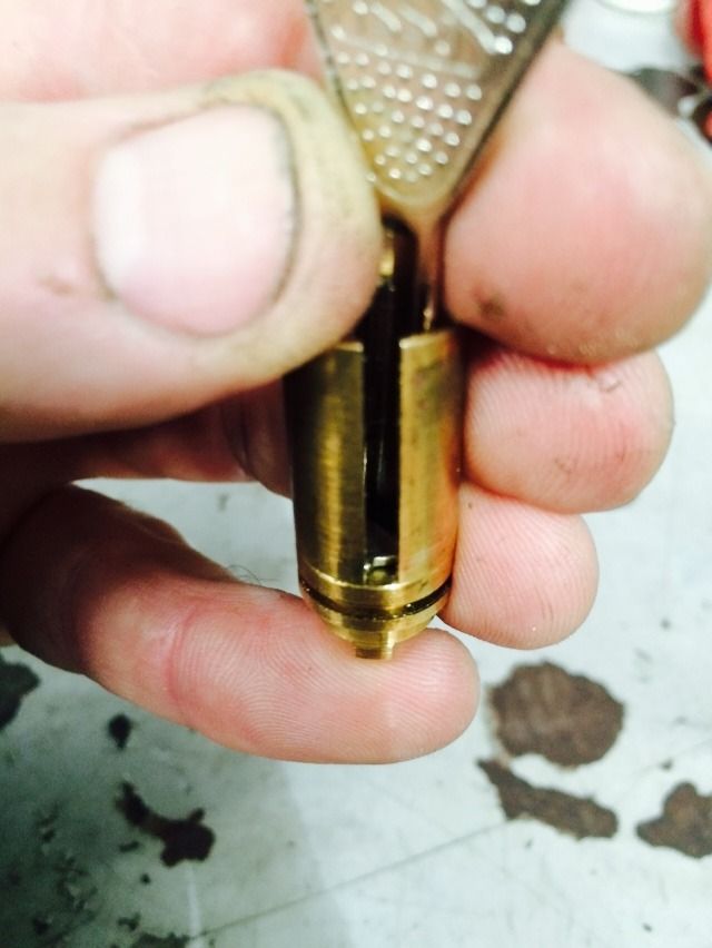
Now use a flat punch that will fit inside the hole in the core to gently push the carrier assembly out.
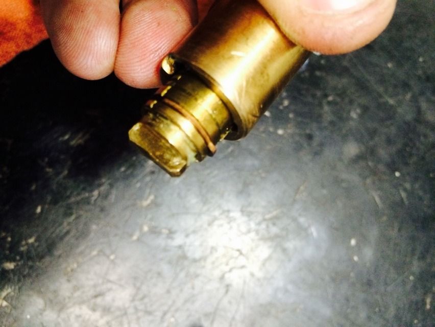
There is a clip that will not allow the carrier out of the core unless the core is in the correct position.
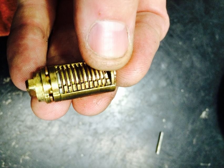
The carrier with the discs and spacers inside, and the side bar on top.
Take out the sidebar, and you can see the discs. Some of the gates in the discs are correctly lined up, some are not.
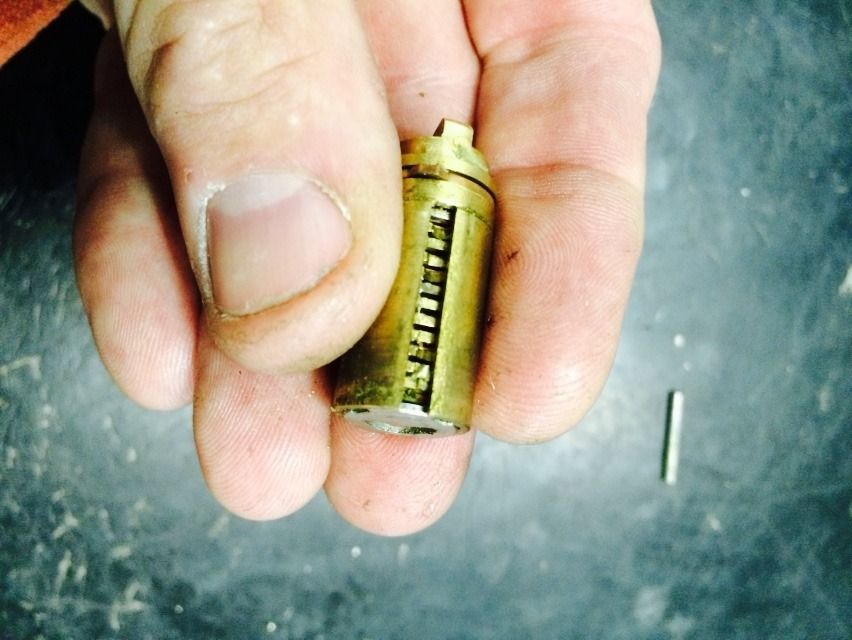
The view from the other side of the carrier. There is a tab on each disc that prevents it from turning too far when the key is being turned counter-clockwise, so they all line up and the key can be removed.
Now for that clip we showed earlier that only allows the carrier to be removed in the correct position. In the not-correct position:
Correct position:
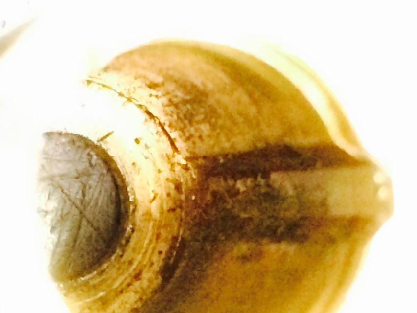
Looking into the carrier with all the discs removed, you can see the groove that the side bar sits in when the lock is locked.
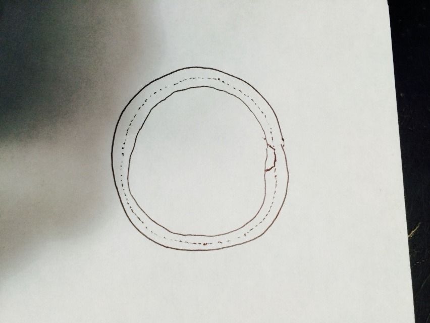
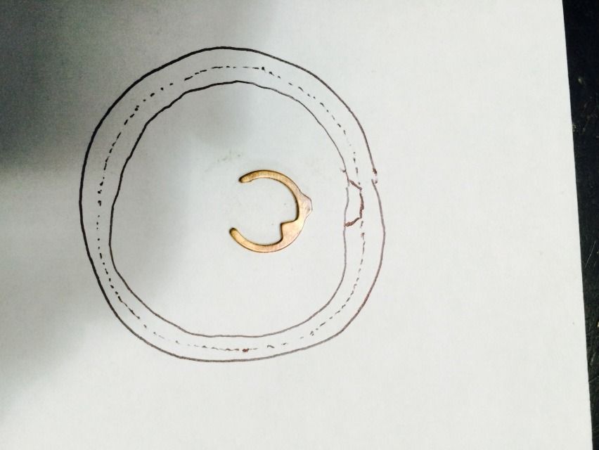
At the bottom of this is a groove that is very hard to get on camera, but will try. But first, here is what you will be trying to see: The solid line is what you can see. The dotted line is a channel cut all the way around the inside of the core that the tab on the clip sits in.
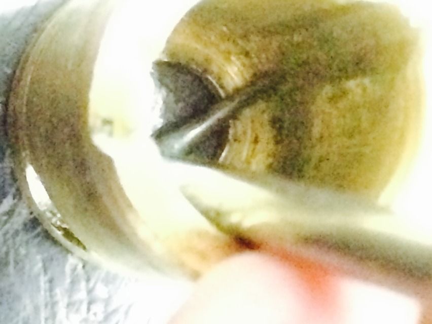
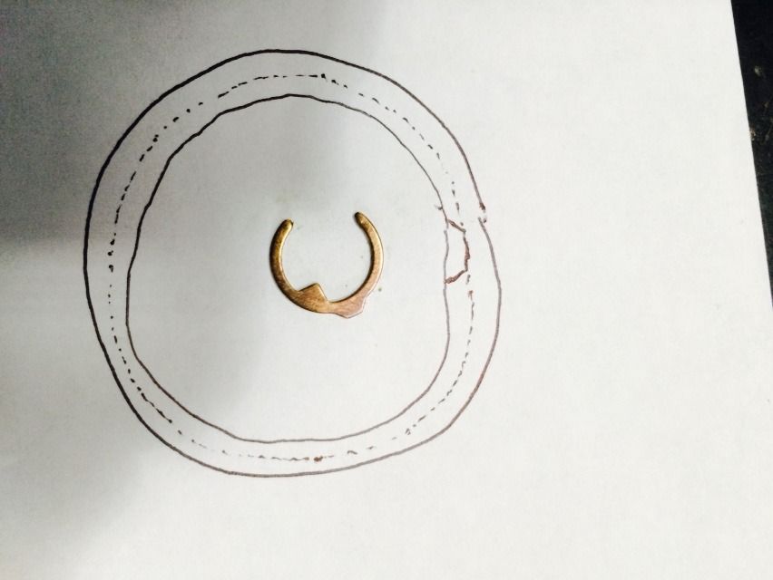
Much easier to lay the part over the drawing.
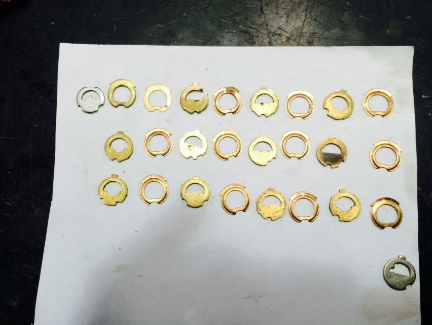
Here all the discs and spacers are laid out neatly. The steel disc with a tab is the outer profile disc located closest to the entrance of the keyway, while the steel disc with a tab is the inner profile disc and is located furthest into the lock (at the tip of the key).
Now for the carrier. Looking into the carrier from the keyway end:
And from the side opposite the side bar.
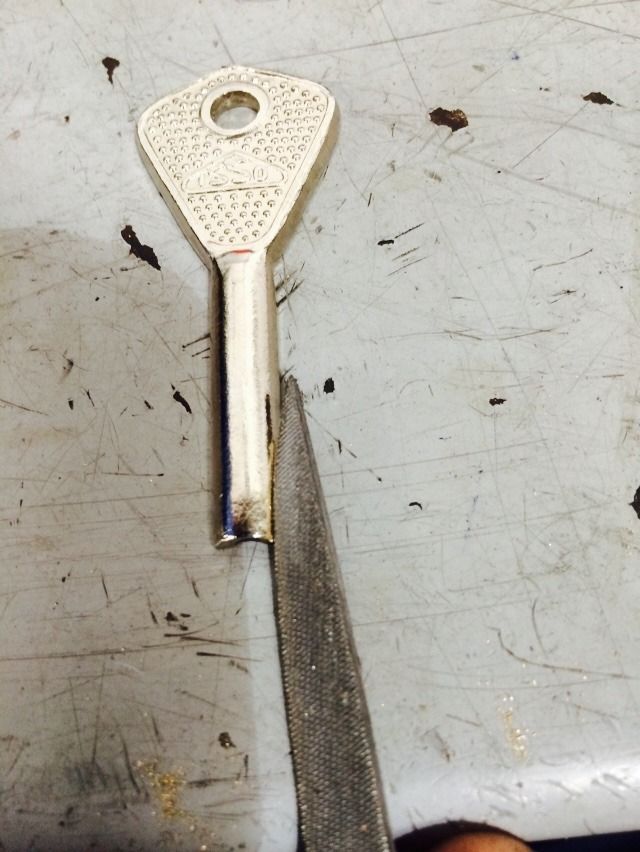
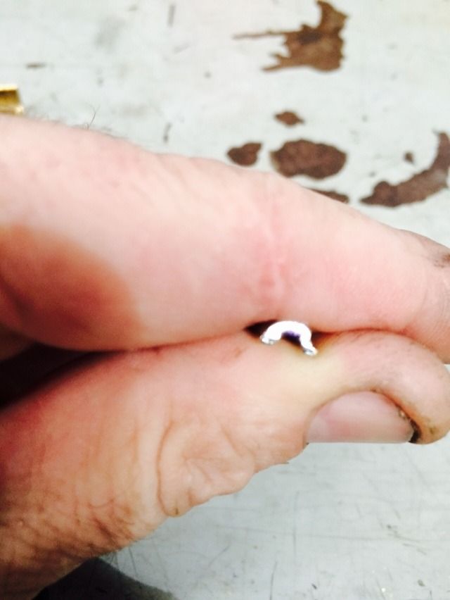
Filing the outer warding on the key. Also file the inner warding.
Put the first disc into the carrier, and insert the key.
The key can be turned to the opposite side until the tab hits the side of the carrier.
Looking in the cutout for the side bar, you can see when the gate in the disc is lined up.
There we are!
That is a profile disc, so it will only line up when at full rotation, so no need to waste time showing that part. Put in a spacer.
And the next disc. Make sure the tabs are all turned counter clockwise until they stop so they are in the 'unlocked' position. You can see that the gate is not lined up properly. Yet.
You can mark a line at each disc so you are sure where you are filing, if you like.
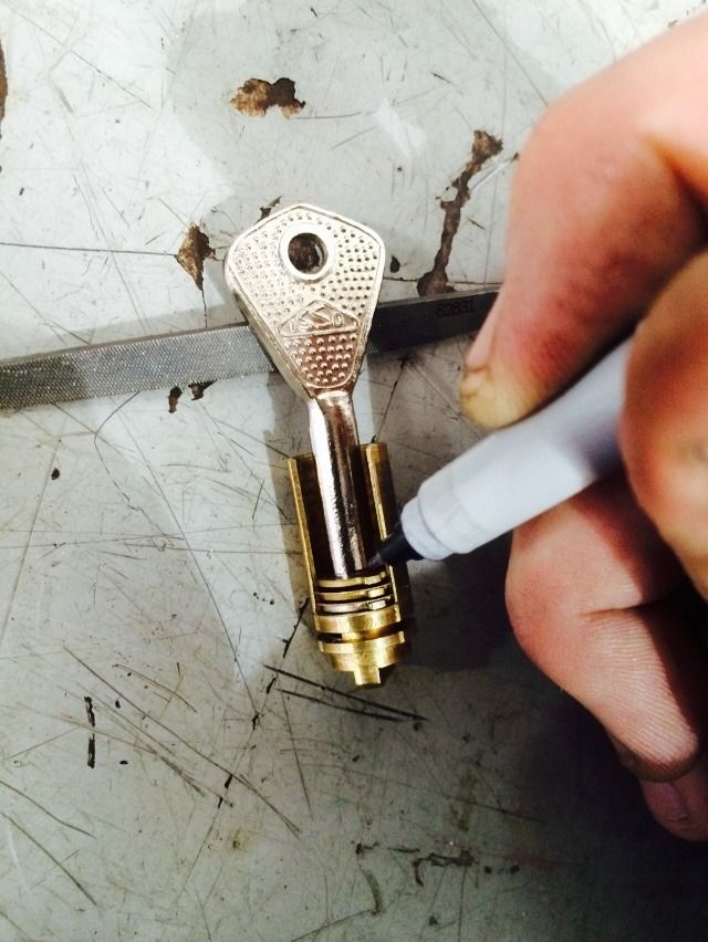
With each disc, you simply insert the key and turn it until it stops. If the gate has passed the cutout for the side bar, you need to file more at that position until when the key is turned, the gate stops at the sidebar cutout. Then you add the next spacer and disc. Repeat until all discs are added and all key bittings are cut. Then your key is done!
Then scroll backwards through this tutorial to reassemble the lock. Remember, you will have to push the core assembly in slightly to compress the spring before tightening the retainer screw. Then you have an Abloy 656 with a working key!
Hope it was worth the read.
Gordon
Again, this is the Abloy 656
This is a massive lock.
Abloy Profile cylinder.
The core assembly is held in by a retainer screw inside this hole.
The screw is reached by having the lock unlocked.
When the retainer screw is backed out sufficiently, the core will pop out a small distance due to a spring.
Then you simply pull out the core. It is not a retainer ring like most Abloy padlocks.
The tailpiece of the core is simple.
Back to the core shortly. For now, let's finish disassembling the padlock. Looking into the lock body, you can see the cam.
Turn the lock so the shackle is up, and tap it on your hand a couple times, and the cam will fall out into your hand.
The cam turned 90 degrees, to the locked position.
This is the top end of the cam, that faces the top of the lock. This spring is what pushes the core/carrier assembly out that little bit.
The tailpiece of the core and the cam fit together like so:
Here are the internals of the lock in the unlocked position.
And locked. (Very simple mechanism).
OK, time for taking the core assembly apart. Looking at the end of the carrier, there is a clip.
And a ramp (when viewed from the side):
Rotate the clip until it starts to go up the ramp. You will need to help it go up the ramp at first using a 90 degree pick.
And keep rotating the clip until it has been removed.
Now use a flat punch that will fit inside the hole in the core to gently push the carrier assembly out.
There is a clip that will not allow the carrier out of the core unless the core is in the correct position.
The carrier with the discs and spacers inside, and the side bar on top.
Take out the sidebar, and you can see the discs. Some of the gates in the discs are correctly lined up, some are not.
The view from the other side of the carrier. There is a tab on each disc that prevents it from turning too far when the key is being turned counter-clockwise, so they all line up and the key can be removed.
Now for that clip we showed earlier that only allows the carrier to be removed in the correct position. In the not-correct position:
Correct position:
Looking into the carrier with all the discs removed, you can see the groove that the side bar sits in when the lock is locked.
At the bottom of this is a groove that is very hard to get on camera, but will try. But first, here is what you will be trying to see: The solid line is what you can see. The dotted line is a channel cut all the way around the inside of the core that the tab on the clip sits in.
Much easier to lay the part over the drawing.
Here all the discs and spacers are laid out neatly. The steel disc with a tab is the outer profile disc located closest to the entrance of the keyway, while the steel disc with a tab is the inner profile disc and is located furthest into the lock (at the tip of the key).
Now for the carrier. Looking into the carrier from the keyway end:
And from the side opposite the side bar.
Filing the outer warding on the key. Also file the inner warding.
Put the first disc into the carrier, and insert the key.
The key can be turned to the opposite side until the tab hits the side of the carrier.
Looking in the cutout for the side bar, you can see when the gate in the disc is lined up.
There we are!
That is a profile disc, so it will only line up when at full rotation, so no need to waste time showing that part. Put in a spacer.
And the next disc. Make sure the tabs are all turned counter clockwise until they stop so they are in the 'unlocked' position. You can see that the gate is not lined up properly. Yet.
You can mark a line at each disc so you are sure where you are filing, if you like.
With each disc, you simply insert the key and turn it until it stops. If the gate has passed the cutout for the side bar, you need to file more at that position until when the key is turned, the gate stops at the sidebar cutout. Then you add the next spacer and disc. Repeat until all discs are added and all key bittings are cut. Then your key is done!
Then scroll backwards through this tutorial to reassemble the lock. Remember, you will have to push the core assembly in slightly to compress the spring before tightening the retainer screw. Then you have an Abloy 656 with a working key!
Hope it was worth the read.
Gordon