FAQ  •  Register  •  Login
UKLockpickers.co.uk Lockpicking supplies such as Lockpicks, tools, and more! COMMANDOLOCK.COM Military grade padlock systems lockpickshop.com A source for lockpicking supplies such as lockpicks, locksmith tools, and more!

LocksportSouth's Stash

<<

LocksportSouth

User avatar

Active Member

Posts: 369

Joined: Wed Dec 02, 2015 6:51 pm

Location: UK

Post Mon Mar 28, 2016 4:05 pm

Re: LocksportSouth's Stash

Riyame wrote:With the magnetic locks one of those front covers will pop out so you can see the internals.


Ah really? I'll have to try that. I figured I'd have to destroy a side which I was reluctant to do as I only have one of these.

Riyame wrote:And with the Abloy I wonder if that is the NATO arrow mark next to the date. I have seen it on Chubb Manifoil as well as Mersey safe locks.


Apparently :) I've heard that it's a Military mark on another forum too - never knew that before so thank you :). You learn something new every day!
<<

LocksportSouth

User avatar

Active Member

Posts: 369

Joined: Wed Dec 02, 2015 6:51 pm

Location: UK

Post Mon Mar 28, 2016 4:25 pm

Re: LocksportSouth's Stash

Do you know if there's a trick to making the cover pop out? I've got mine in front of me and have tried pressing the front that isn't sealed, digging at the edges with a screwdriver but I can't get anything behind the plate. The lock is unlocked, there doesn't seem to be any kind of fixing inside the shallow shackle hole or anything like that?
<<

Riyame

Keeper of the Bests / Supreme Overlord of Small Format Interchangeable Picking Nightmares

Posts: 2164

Joined: Sun Jul 24, 2011 11:16 am

Location: Canada

Post Mon Mar 28, 2016 6:50 pm

Re: LocksportSouth's Stash

LocksportSouth wrote:Do you know if there's a trick to making the cover pop out? I've got mine in front of me and have tried pressing the front that isn't sealed, digging at the edges with a screwdriver but I can't get anything behind the plate. The lock is unlocked, there doesn't seem to be any kind of fixing inside the shallow shackle hole or anything like that?


Hold the shackle in your hand and smack the bottom edge of the lock against a table or something. You should be able to see a seam to tell which side comes out as the other side is cast with the cast.

It is a fairly snug pressure fit so it might not come out at all.

If you don't mind a very slight destructive entry you could drill a small hole in the bottom of the side that comes out and use a dental type pick to pry the cover up.
PhoneMan: I always knew I'd say something stupid and it would be someone's sig
macgng: i am an equal opportunity pervert
macgng: aww fuck thats goin in someone sig :-(

If life gives you melons, you might be dyslexic.
<<

LocksportSouth

User avatar

Active Member

Posts: 369

Joined: Wed Dec 02, 2015 6:51 pm

Location: UK

Post Mon Mar 28, 2016 6:57 pm

Re: LocksportSouth's Stash

Riyame wrote:
LocksportSouth wrote:Do you know if there's a trick to making the cover pop out? I've got mine in front of me and have tried pressing the front that isn't sealed, digging at the edges with a screwdriver but I can't get anything behind the plate. The lock is unlocked, there doesn't seem to be any kind of fixing inside the shallow shackle hole or anything like that?


Hold the shackle in your hand and smack the bottom edge of the lock against a table or something. You should be able to see a seam to tell which side comes out as the other side is cast with the cast.

It is a fairly snug pressure fit so it might not come out at all.

If you don't mind a very slight destructive entry you could drill a small hole in the bottom of the side that comes out and use a dental type pick to pry the cover up.


Funnily enough, at the same time I was discussing this here the same topic came up on a UK forum I'm on and I ended up opening up the lock and doing a breakdown of the workings.... Then it turned out the other guy I was chatting to had also opened his up. Then someone else posted a link to another thread that also had a video discussing the operation - funny old night, haha!

For everyone's benefit I'll put my write-up here too:

----

Okay, so, I couldn't wait until tomorrow :D.
Just took this out to the garage and got it apart. I've gotta hand it to IFAM, they're tough little buggers. I thought the "open" front plate would be able to be removed but nope, the front and back plates are well sealed in there. Anyway, not here to discuss destructive opening obviously, but hopefully it's okay to discuss the insides :).

I've attached four photos - the first is simply a shot of the lock open:
01 Open.JPG


and the third is a close-up of the little magnetic pin-things inside the lock that interact with the key.
03 Pin.JPG


The fourth shows the lock in the unlocked position. The second photo I will use to demonstrate how the lock works, and I've pre-numbered the parts to help explain how the lock works. The numbered parts are:

01 - The outer side of the lock, where the key attaches
02 - The key rods which interact with the key and the actuator
03 - One type of magnetic pin; these react to the magnets in the key and push or pull the rod accordingly
04 - The same pin as 03 but with reversed magnetic polarity. The holders for these are also different
05 - The actuator / locking bolt
06 - A spring-loaded leaver that acts on the actuator / locking bolt
07 - Shackle locking hole

02 Diagram.JPG


Note that where 02 come out the bottom and also above the horizontal bar near the top of the lock (above which 04 and 03 attach to 02) - on that horizontal bar you can also see a thin layer of copper. The 02 bar actually thins right down in the middle of the bar, presumable to hold the rod in place and stop it falling out.

The shackle does not lock in the "usual" place, instead, the locking position for the shackle is at the back of the lock, at position 07. 05 acts as the locking bar which slots into 07, holding the shackle closed. The shackle actually opens under reverse spring tension - the spring holds the shackle closed, and it must be pulled on with quite some force even when unlocked to release the shackle.

By default, the 06 spring loaded leaver holds 05 locking bar actuator in the Unlocked / forward position. The locking bar 05 must be pushed back on to enter the locked position. Where the 02 rods meet the flat horizontal plate on 05, there are several small divot points in the metal, sunken in but fairly shallow, surrounding a central hole through which the rod can fit, kind of like a flower. When these bars 02 are lined up straight, the ends of then will catch on the divots in 05 and force the bar back, causing the large block at the back of 05 to slot into the shackle hole 07, keeping the lock shut.

At the front end of the bars 02 are small magnets encased in a rubber surround - 03 and 04. You can see a close up photo of one of these in photo 3. The rubber enclosure of these magnets has a small hole which allows the 03 and 04 units to be pushed onto the end of the 02 bars. There are two types of pins (one for north and one for south pole magnet, I assume). In my lock, 04 is the odd one out, with the others being 03. Whereas the 03 magnets fit directly onto 02 poles, the 04 magnet unit slots into that little red "cup" in 04.

When a key is applied to the side of the lock 01, the magnets inside the key push or pull on the magnets inside the lock 03 and 04. Assuming the right key is used, all four of the 03/04 units will be pulled straight forward, up against the edge of the lock body. Because the pins 02 are now aligned straight, the ends of them are able to slot through the holes in the locking pole 05. Since the spring loaded lever 06 is always "pulling" the locking bar 06 into the open position, said locking bar is now able to pop forward (towards side 01), allowing the shackle to be pulled up (under spring tension) and out of the body.

Note that in these photos, the locking mechanism is in the locked position. Refer now to photo 4:
04 Unlocked.JPG


When the rods 02 have been correctly aligned and slip through the holes in 05, the bolt 05 retracts quite a long way (I only just realised at this part of the analysis that the lock was "locked" before, hence this bit may seem a little disjointed, apologies). Once the lock is in the unlocked position, it is only re-locked when the shackle is re-inserted. Notice how the other (short) end of the spring loaded lever 06 now sticks out quite far? When the shackle is returned to the closed position, the spring tension will snap the shackle closed, As the long shackle side retreats into the lock body, it pushed on the end of the spring-loaded lever 06. This pulls the locking bar/actuator 05 back into the locked position and the locking rods 02, now not held in place by the key, will flop around and catch in the divots in locking back 05, re-locking the lock.

Something else I've noticed is that the location of the holes in locking bar 05 are not centrally aligned - see new photo 05. If the rods are not actually being held straight but instead at an angle, that might imply that this lock uses a modified form of the rotational magnets used in the EVVA MCS. Interesting indeed!

05 Flower.jpg


Anyway, that's the analysis I've had so far. May you find it interesting :).
You do not have the required permissions to view the files attached to this post.
<<

Riyame

Keeper of the Bests / Supreme Overlord of Small Format Interchangeable Picking Nightmares

Posts: 2164

Joined: Sun Jul 24, 2011 11:16 am

Location: Canada

Post Mon Mar 28, 2016 7:21 pm

Re: LocksportSouth's Stash

Dang, you really did a job getting that one open :lol:
PhoneMan: I always knew I'd say something stupid and it would be someone's sig
macgng: i am an equal opportunity pervert
macgng: aww fuck thats goin in someone sig :-(

If life gives you melons, you might be dyslexic.
<<

GWiens2001

User avatar

Lock-Goblin-Gordon
Lock-Goblin-Gordon

Posts: 3795

Joined: Thu Oct 25, 2012 9:05 pm

Location: Arizona, United States

Post Tue Mar 29, 2016 6:35 am

Re: LocksportSouth's Stash

Have one of the magnetic locks which had the front cover removed and a plastic cover installed, so all the internals show. They are pretty cool inside. Want me to dig it out for a pic?

Gordon
Just when you think you've learned it all, that is when you find you haven't learned anything yet.
<<

LocksportSouth

User avatar

Active Member

Posts: 369

Joined: Wed Dec 02, 2015 6:51 pm

Location: UK

Post Tue Mar 29, 2016 9:56 am

Re: LocksportSouth's Stash

Riyame - Ahah, that's my infamous DIY skills at work - "A less elegant weapon, for a less civilized age" :D
Gordon - Sure thing :) Always cool to see new lock picks!
<<

LocksportSouth

User avatar

Active Member

Posts: 369

Joined: Wed Dec 02, 2015 6:51 pm

Location: UK

Post Tue Mar 29, 2016 9:59 am

Re: LocksportSouth's Stash

Yet another Abloy! I totally forgot that the 340 is one of the new range that I didn’t yet have. Ordering this one was a bit of a palava as it didn’t turn up for ages, but it got here in the end – and it’s a lovely lock:

Image

So yeah, Abloy 340, using the Protec core – if you’ve seen any of my other Abloy posts, you know the drill :).

Image

Image

Image

Image

Image

Image

I did strip this one down, at least to the cylinder level, as well. Just for fun. Same process as the others – remove the set screw from the side and unscrew the bottom plug:

Image

Image

The cylinder:

Image

Actuator and spring:

Image

Pop it back in:

Image

Image

It’s in great condition, another lovely addition to the growing Abloy collection!
<<

LocksportSouth

User avatar

Active Member

Posts: 369

Joined: Wed Dec 02, 2015 6:51 pm

Location: UK

Post Tue Mar 29, 2016 1:35 pm

Re: LocksportSouth's Stash

Ok – cool update today! I have a Medeco Deadbolt, which I won via a contest on another forum. I’ve stripped it down, cleaned it up, and put it back together... With a little surprise to boot!

So, let’s take a look at her!

Image

I don’t know a great deal about American style deadbolts, but the operation is fairly simple – the part closest to the camera is a locking cylinder inside of an outer bezel, and it mounted on the outside of the door. This specific lock has been mounted in a plexiglass display ring, and the part that is clear/see through in the photo is where the door would normally be. The bolt protruding from the right hand side of the lock is embedded into a mortise in the door, and at the back (not visible in this photo) is a similar bezel to the front, except that it has a thumbturn style catch, which goes on the inside of the door. Either the actuator rod on the back of the cylinder, or a rod which protrudes from the thumbturn will rotate the mechanism inside the bolt unit and throw or retract the bolt – as it’s a deadlock it’s not venerable to usual latch bypasses.

This specific deadbolt is a Medeco (very cool!) and comes with the key, front bezel/lock, bolt, plexiglass viewing ring and rear latch. The latch doesn’t currently work (the actuator tailpiece is too short to reach the bolt) and it’s a bit dirty inside, so let’s open it up and see what we can do :).

First off, some more pics. Here’s the lock from the front, bolt thrown. This is how it would look attached to the door (with the bolt unit obviously being in the door itself). Love that thick and heavy duty look to both the lock bezel and the bolt itself:

Image

Looking down through the plexiglass, you can see the workings inside. You can also see the rear thumbturn handle from this angle:

Image

In the edge of the thumbturn, you can see a hex nut which holds it to the spindle. Let’s take that off...

Image

Image

Underside of the thumbturn:

Image

With the thumbturn removed, we can see the centre spindle (as well as the tailpiece locked in with another set screw) and a thin brass disc which covers the screw holes:

Image

The metal disk appears to have been held on with glue once upon a time. With it removed, you can now see the disassembly bolts holding the front part on:

Image

Remove the bolts...

Image

Image

And remove the back plate. We can now see the bolt attached inside. Note the middle of the brass ring in the middle has a flat cutout – to accept the flat tailpieces on the thumbturn and lock cylinder:

Image

Rear of the thumbturn plate showing the back of the centre spindle and the tailpiece:

Image

The bolt itself:

Image

Looking down inside the plexiglass sleeve towards the back of the key/lock actuated side:

Image

The plexiglass sleeve:

Image

Looking towards the back of the locking section, without the plexiglass. Note the metal surround, which would need to be morticed into the door:

Image

The front bezel section, with the locking cylinder removed (it simply slides out):

Image

Looking at the locking cylinder, we can see that the pin chambers are loaded individually using set screws – handy!

Image

The back of the cylinder. Actuator plateholds the tailpiece stick and is held onto the lock itself with two screws:

Image

Cylinder from the side. Nice and thick & chunky!

Image

Removing the set screws to unload the pin chambers:

Image

Image

Good ol’ Medeco pins :). In this case, a mushroom driver and typical Medeco wedge key pin.

Image

All the pins unloaded – two mushroom and 4 standard drivers, also the end driver is stainless steel for anti-drill protection:

Image

The key:

Image

Actuator plate & tailpiece removed:

Image

Image

Rear of the plug & cylinder housing:

Image

Overall shot of the plug & Key (sidebar still intact), housing, actuator & tailpiece, pins, and those two half-moon pieces are anti-drill plates which were round right at the front of the cylinder housing:

Image

Closeup of the plug and anti drill plates:

Image

Plug empty, note the three anti-drill rods towards the front near the key:

Image

Here in the housing, you can see the milled out line for the sidebar as well as the indent just under the lip of the front, where the anti-drill plates sit:

Image

Side bar & springs removed, put together with the front anti drill plates:

Image

Cylinder with sidebar removed:

Image

Right! That’s stripped down as far as it can be. Now it’s time to give this a clean up! I opted for partially filling a pot with GUNK and placing the parts in, allowing them to soak overnight:

Image

Image

Here we are, the next day, cleaning off the pins & bits with a tissue. Lots of black gunk coming off – good good!

Image

Pile ‘o’ shiny parts!

Image

Image

I mostly re-assembled this off-camera. However I did make an interesting discovery. Here’s the tailpiece in the rear thumbturn handle – it’s too short to fit into the cylinder, and that’s why it didn’t work, freely spinning in the housing rather than . Go back and look at the original photo of this – notice how in that pic the large “wings” of the tailpiece are flat against the middle round thingy? And in this photo, see how it sticks out further? It turns out that the tailpiece is held into this round centre column with a set screw and upon loosening it, it seems that the tailpiece can come out much further – far enough to link into the bolt!

Image

There’s a problem, however. The handle itself needs to connect into the rear of the back plate, which is held in with a C clip. Sadly I don’t have any spare C-clips... But after cannibalising a spare half-euro cylinder that I had lying around, I managed to find one!

Image

It doesn’t fit perfectly, but it does the job – just about:

Image

Re-assembled, the lock now works with both the key AND the thumbturn!

Image

Image

Image

Image

It’s also super shiny and clean now :).
<<

LocksportSouth

User avatar

Active Member

Posts: 369

Joined: Wed Dec 02, 2015 6:51 pm

Location: UK

Post Wed Mar 30, 2016 3:39 am

Re: LocksportSouth's Stash

Today we’re taking a look at the Sargent & Greenleaf 8088 combination padlock. We’ll also be taking a look at the 8065 soon, and here’s a pic of both boxes together:

Image

The S&G combination padlocks are interesting. Whilst they don’t have especially thick shackles and can be destructively cut or smashed open if one were truly inclined, that’s not their purpose. They are typically used on military filing cabinets and other secure document storage – situations where it isn’t necessarily vital to prevent access (as they will usually be on filing cabinets etc already housed in a secure military compound), but it IS important to provide a “security seal” – absolute proof that someone has forced their way into a container. To that end, these locks are usually stamped with a unique ID so breaking and replacing them will still be visible to the lock controller. In the height of the cold war, the military went to even greater lengths to stop spying and other surreptitious entry but we’ll get to that in the 8065 review.

So, back to the 8088. Here are some box shots – this is the original box afaik:

Image

Image

Image

Image

Unboxed, we see quite a small selection of contents: the box itself, the lock, an instruction sheet and a change key (for changing the combination):

Image

Instructions:

Image

Image

Change key – the top section is the bit that goes into the change key hole:

Image

“8077&8088” – the locks that it works with:

Image

Front view:

Image

Side:

Image

Image

Top:

Image

Rear. The small keyhole looking shape on the bottom left, next to two rivets, is where the change key is inserted. However the keyhole is currently blocked by a metal disk which is rotated out of the way by lifting that metal button dial on the right-centre. However that is itself unable to be moved unless the lock is unlocked:

Image

Image

The default combination for S&G combination locks is usually 25-0 or 10-20-30. The instructions explain how this is done, but basically you start off by rotating the dial left (counter-clockwise) at least 4 revolutions (I tend to keep spinning it for a while just to be sure it has picked up all the disks), and stop on the first number of the code (for 25-0, that would be 25, for 10-20-30, that would be 10). For 25-0, you then turn the dial right (clockwise) until it hits 0, and then pull on the shackle. For 10-20-30, you would instead turn the dial right (clockwise) for 3 revolutions until it hits the second number (in this case, 20), then back left 2 times to 30, then right to 0 and pull open the shackle. Note that a revolution occurs whenever you pass a number.

This 8088, which is an older generation, was 25-0. (the newer ones are 8077 – specifically the 8077A, 8077AC and 8077AD, which is the newest. There may also be an AB, but I haven’t seen one so far). I believe that either older or newer gen are generally 25-0, and the other is 10-20-30, but I can’t remember which offhand.

So, in our case, we dial 25-0 and pop the shackle open:

Image

The shackle doesn’t go down too deep. Remember, the goal is evidence of break-in, not necessarily rock-hard security:

Image

For fun, let’s change the combination. First of all we have to flip the lock over, with the shackle open:

Image

Then we need to lift that metal button dial to get access the change key slot. As you lift the button, you’ll see the change key hole open up:

Image

We can follow the instructions to make sure we do this correctly:

Image

I think the first and most important thing is to decide on a new combination and write it down! There’s no getting into these if you forget the combination. Since this is one of the older 25-0 combinations, I decided to go for 10-20-30, the modern “standard” combo, for this lock:

Image

Once you’ve pulled the opening button back, you can close the shackle to “pin” the lock in the change-hole-open position. Be careful not to accidentally do this when locking the lock for “normal” operation or it will be vulnerable to being changed! (it’s not that easy to do since the button is under strong spring tension):

Image

We now need to dial the correct combination in again, but using the change index rather than the opening index. The opening index is the “tree” or arrow shaped main line on the front of the lock, at the 12 o’clock position above the dial, which you use to dial in the combination. The Change index is the small line to the left of that, at about the 11 o’clock position. Dial the same code as before – except using the change index as the reference rather than the main opening index:

Image

Then, slot in the long side of the change key into the change key hole:

Image

And rotate it clockwise until the edge of the key hits the stop.

Image

We now need to dial the new combination into the lock, using the CHANGE index. Spin left 4 times to 10:

Image

Then right 3 times to 20:

Image

Then left again, twice, to 30:

Image

Back to zero, then unlock and remove the key:

Image

Image

Now it’s time to dial the new combination using the opening index!
10:

Image

20:

Image

30:

Image

0:

Image

And open:

Image

And we’re all done! I’ve never really owned or been interested in these locks, but since buying these and learning how they operate and are changed, it’s increased my appreciation for them immensely!
<<

LocksportSouth

User avatar

Active Member

Posts: 369

Joined: Wed Dec 02, 2015 6:51 pm

Location: UK

Post Wed Mar 30, 2016 10:13 am

Re: LocksportSouth's Stash

After that cool 8088, we should move on to the other lock hinted at in that post... The Sargent & Greenleaf 8065:

Image

I love this lock. It’s quirky and interesting and cool. We’ll get on to some of the reasons why later in this post.

Box is a little damaged sadly:

Image

Image

Image

Image

One of the box flaps is completely torn off, but I do still have it:

Image

Unboxed, we have the lock, instructions, and a small stapled bag:

Image

Instructions:

Image

Image

Image

It’s a bit more complex than the 8088!

What’s in this packet, I wonder?

Image

Image

Change key and screws... Why screws, you may ask? Well, this lock is designed to be fitted directly onto a filing cabinet or drawer etc, and once you unlock it, you can slide the drawer open. I’ll explain more as we move on.

Front of lock. Notice how there’s an opening index mark every 90° around the bezel? That’s because you can mount this lock in any one of four directions – upright, on the left or right hand side, or upside down, depending on where your drawer/frame/etc is located. The button is used for opening the lock and also opening the back for the code change process. You’ll notice also that you can’t see the dial numbers in this position – this lock has an anti-spy ring, and only the top area between the 10 o’clock and 2 o’clock position can be seen.

Image

Side of lock. The wider/larger part that covers 80% of the height of the back of the lock is the back plate and protects the code change area, it also can be screwed on using those screws from earlier to hold the lock in place.

Image

Back of the lock. In addition to the model number and the date of manufacture (dayum! 1967 and still looking shiny as all hell), you can see a black rectangular hole – that’s where the shackle bar goes.

Image

You can see the inside of the shackle area better in this photo. It’s not obvious yet how this lock works, but when locked a round metal shackle bar slides in vertically from roughly the centre point of the hole, from the lock body, up onto the top section. When the lock is fitted with its back onto a drawer, the drawer can be slid back allowing a staple plate to slide into this hole, and the vertical bar will lock it in place.

Image

Top of the lock with a unique ID stamped – this will allow the security personnel to quickly identify if the old lock has been smashed open and replaced with a new one:

Image

Front of the lock, showing the dial peephole:

Image

In this pic you can see the shackle bar rising up as previously discussed:

Image

Shackle locked:

Image

Remember – this isn’t the usual kind of lock. It’s not really for locking chains or hasps & staples – it’s specifically to fit onto cupboards, drawers and filing cabinets, and will work with a specially shaped staple fitted to the drawer or frame, which will slot into this open hole when the drawer is closed.

The opening and code change instructions are complex and I won’t attempt to recreate them here for fear of explaining it wrong. However I did decide to change the combo on this lock (which was set to the default 10-20-30) just to check that I could, and that I knew how to. Once you’ve dialled in the correct combination, half-press the button so it’s between the two red lines and rotate the dial to remove the back cover:

Image

Image

Look at that massively thick back cover! The three deep divots are where you can screw through to fit the back plate to a cabinet. Fun fact: Whilst all these 80** series locks are designed to be anti-spy and to prove whether someone unauthorised (possibly a mole) has been digging where they shouldn’t be, in the height of the Cold War fears and nuclear golden age, there was a concern (whether real or imagined) that Russian spies were infiltrating these facilities and using a portable radioactive isotope and photographic paper to expose the lock to radiation with the paper behind and grab essentially an X-ray of the lock’s insides, allowing them to secretly decode the combination and get access to the lock. In response to this, the 8065 (and I believe all 8077 locks going forward) were designed with lead plates inside to prevent that kind of attack. How cool is that??

Moving on then! Here’s the back of the lock with the back cover removed. The small round button thingy is a bar which comes out and locks the back cover on when the lock is locked (note the square cutout in the previous back plate picture). The oddly shaped keyhole thing is the change key slot. You can actually decode the disks through this keyhole, hence why the back plate is added.

Image

Closeup of the change key hole. You can see the disks deep inside!

Image

When the lock is prepared, you can insert and rotate the change key:

Image

Image

Since the original code was set to 10-20-30, and I’m not sure whether it’d be possible to go “back” to 25-0, I decided upon a new code – 10-30-50:

Image

Setting the code via the change index (a small step to the left as seen in the 8088 post):

Image

Image

Image

Image

Remove the key:

Image

Test the lock:

Image

And we’re done! What an awesome lock.
<<

LocksportSouth

User avatar

Active Member

Posts: 369

Joined: Wed Dec 02, 2015 6:51 pm

Location: UK

Post Wed Mar 30, 2016 5:23 pm

Re: LocksportSouth's Stash

Here's a little sneak peek at a project I'm working on... And a glimpse at some locks I've maybe not talked about yet ;)

Image
<<

GWiens2001

User avatar

Lock-Goblin-Gordon
Lock-Goblin-Gordon

Posts: 3795

Joined: Thu Oct 25, 2012 9:05 pm

Location: Arizona, United States

Post Wed Mar 30, 2016 5:42 pm

Re: LocksportSouth's Stash

Drooling over those Ingersoll locks, as well as the Ruko 4-5. :drool:

Gordon
Just when you think you've learned it all, that is when you find you haven't learned anything yet.
<<

LocksportSouth

User avatar

Active Member

Posts: 369

Joined: Wed Dec 02, 2015 6:51 pm

Location: UK

Post Thu Mar 31, 2016 6:00 am

Re: LocksportSouth's Stash

GWiens2001 wrote:Drooling over those Ingersoll locks, as well as the Ruko 4-5. :drool:

Gordon


*Comes over with tissues and wipes the locks off* :mrgreen:

Me too though! Do you know why it's called the 4-5? AFAIK the SKAFOR ratings only go up to 4 (red stripe) so I'm wondering if the "-5" is a theoretical level - like, they judge the lock as rating higher than the open shackle (4641). The numbering system is also off for the shutter lock (being 56 rather than 46). I discuss this a bit more in my post for that lock but I'm just curious if you know why it's rates this way :)
<<

LocksportSouth

User avatar

Active Member

Posts: 369

Joined: Wed Dec 02, 2015 6:51 pm

Location: UK

Post Thu Mar 31, 2016 7:24 am

Re: LocksportSouth's Stash

Let’s kick off the final phase of new updates with a 
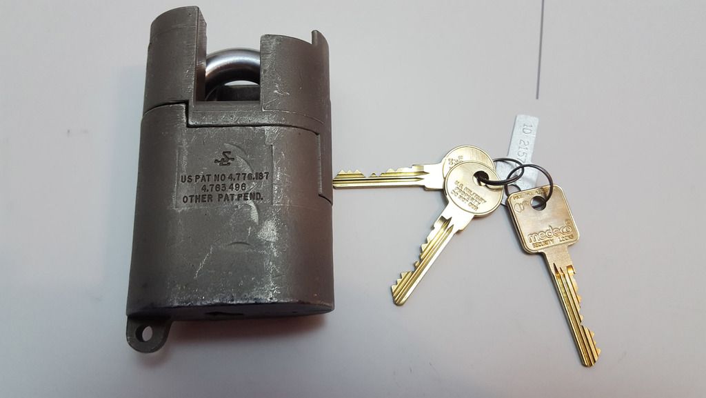
Sargent & Greenleaf 833:

Image

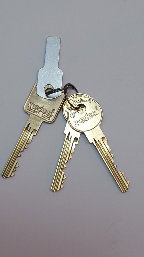
This one came from a forum member and is not in its box but it does come with all three original keys and the keycard. These S&G locks (Medeco cylinders) come with two operator’s keys – the ones with the round bow – which are purely for locking and unlocking the lock, and they also come with a control key – the square bow one – which, as well as locking and unlocking the lock, will also allow the lock to be disassembled for servicing and to change the core or parts inside. Interestingly the difference between the two types of keys isn’t in the bitting at all – both keys are cut identically – but (depending on the exact model) is usually just a small cutout or notch near the bow of the key, on the reverse side to the bitting, or a shoulder vs not-a-shoulder in the same place. This does mean that you can usually modify an operator’s key into a control key, if you wish.

The S&G 831, 833, and 951 (the chronological successors of the series) are super heavy duty, weigh a tonne (around 2.2kg or so each) and are resistant to everything from cutting and drilling to exotic liquid nitrogen attacks. I believe they’re usually used on ammunition bunkers and the like, although you can buy them for civilian use such as high security installations.

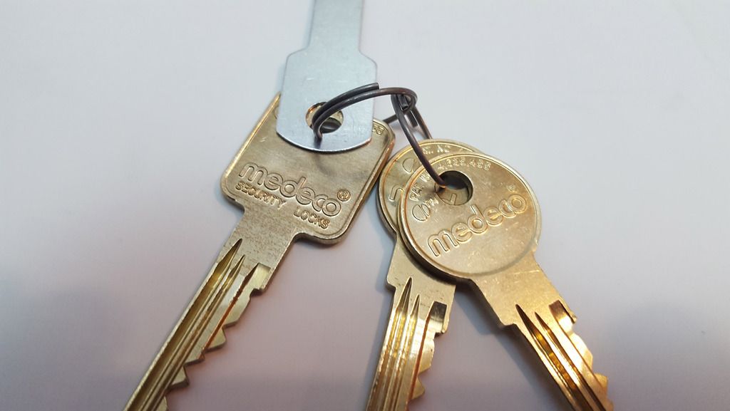
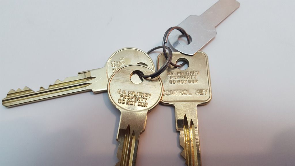
Close-up of the keys:

Image

It is typical, in my experience, for the control key to be on a separate keyring to the operator’s keys – along with the code card. It is, after all, designed to be kept separately and given only to authorised personnel. These are 6-pin Medeco cylinders although I have been unable to ascertain which key profile these are (e.g. classic, Biaxial, M3 etc) or which keyway types they are (R1, D4, S1 etc). Nice shiny keys!

Image

Image

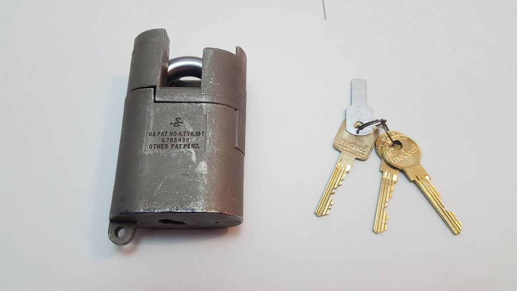
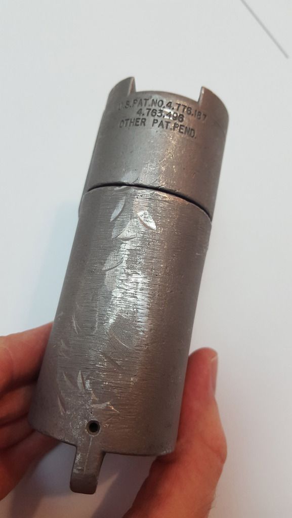
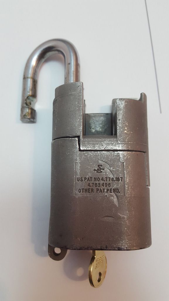
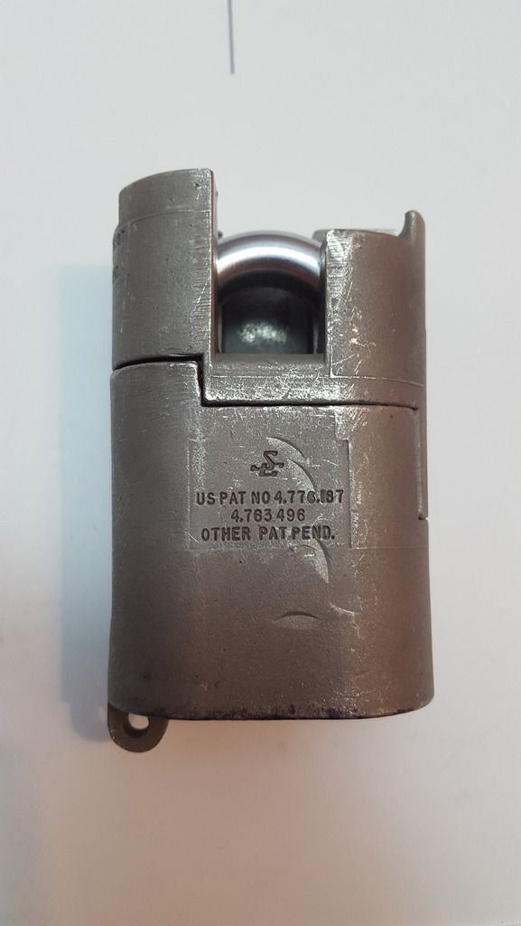
Back of the beast (or front? I’m not sure what counts as the front and the back tbh):

Image

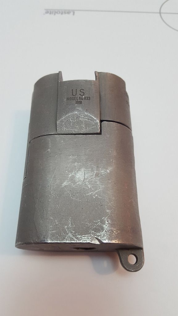
It’s a little scratched and beat up but still works perfectly – that’s solid, precision engineering for you!

The side, also a bit dinged:
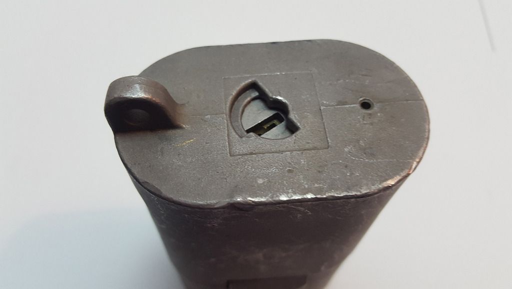
Image

Top of the lock:

Image

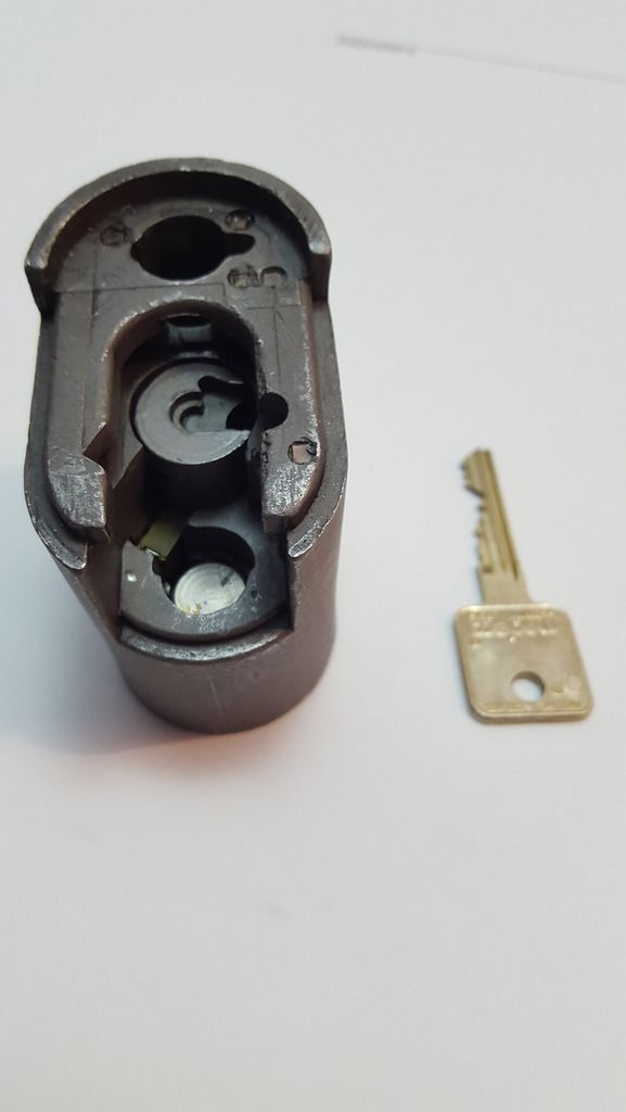
Bottom, where you can find the keyhole, drain hole, and my personal nemesis due to its prevention of the lock being freestanding, the chain anchor. The oddly shaped keyhole cutout is due to the way the operator and control key works.

Image

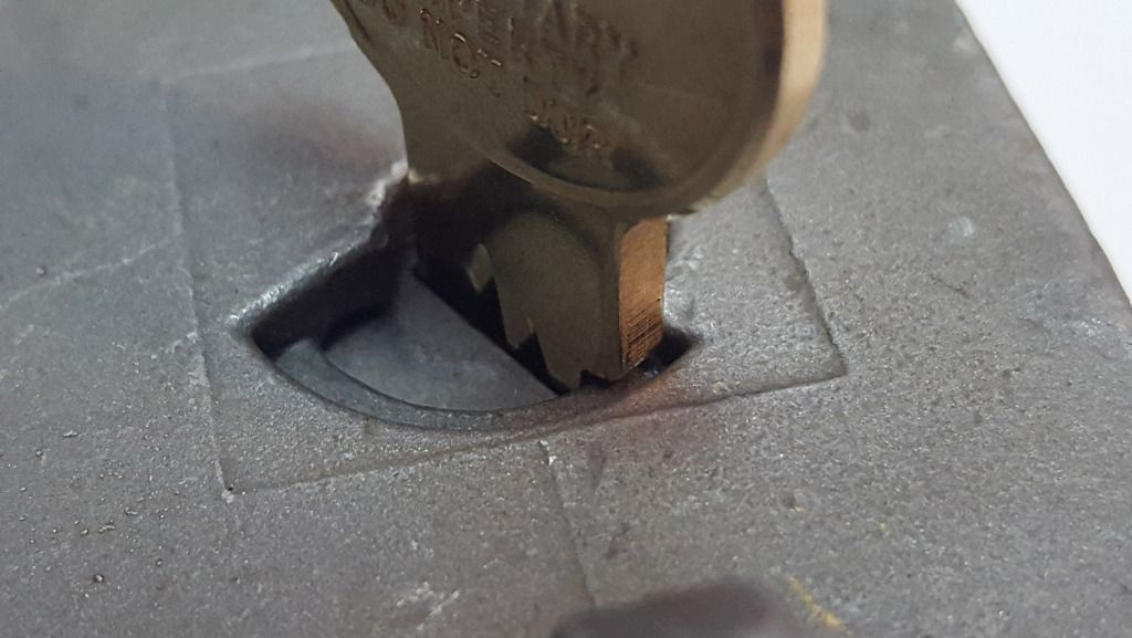
To see what I mean, take a look at the following photo. The operator key is inserted. Notice how the protrusion (shoulder) on the back of the key prevents it from turning past that block off point? It can rotate clockwise but not anti-clockwise. That’s the direction to open the lock, whereas the control key, which does not have a shoulder, can clear that obstruction and turn anti-clockwise too, allowing it to turn the actuator to a position where the lock can be opened.

Image

Shackle is a little dirty:

Image


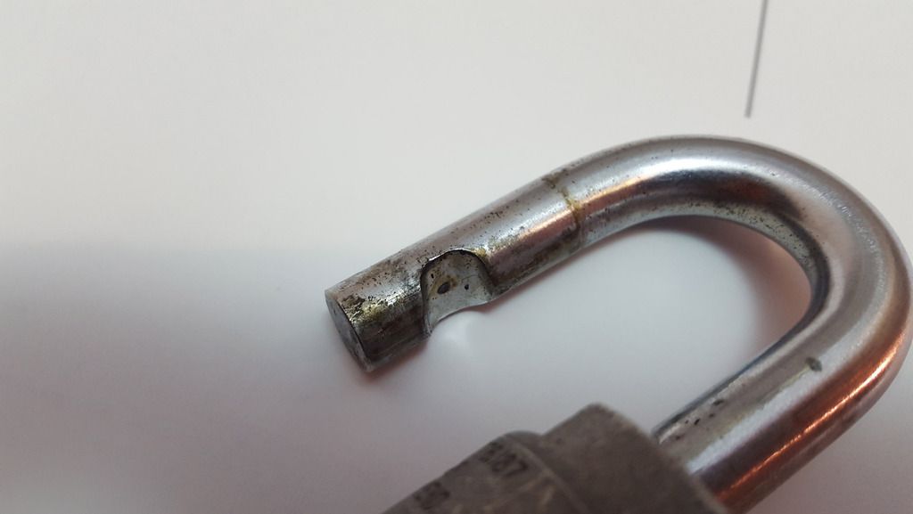
Turned to the opening position, the shackle can be freed and swung open. It’s closed shackle and key retaining, and the shackle can only “exit” the body in one direction. Also note the big “seam” in the middle of the lock that makes it look like the body is made from two pieces...

Image

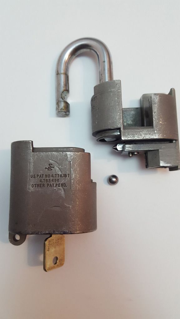
With the control key inserted and rotated in the opposite direction, the two halves of the lock body slide apart and the lock can be stripped and serviced. Watch out for escaping ball bearings!

Image

Side of the body. There’s supposed to be an anti-drill ceramic rod in that cutout slot, but it’s missing unfortunately:

Image

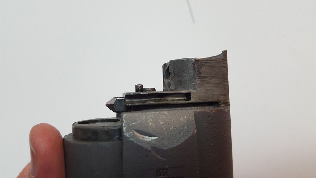
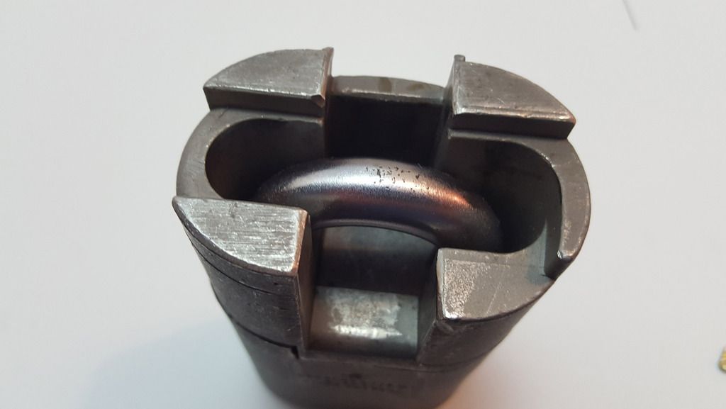
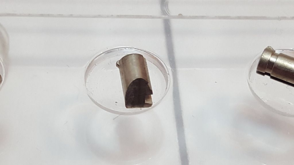
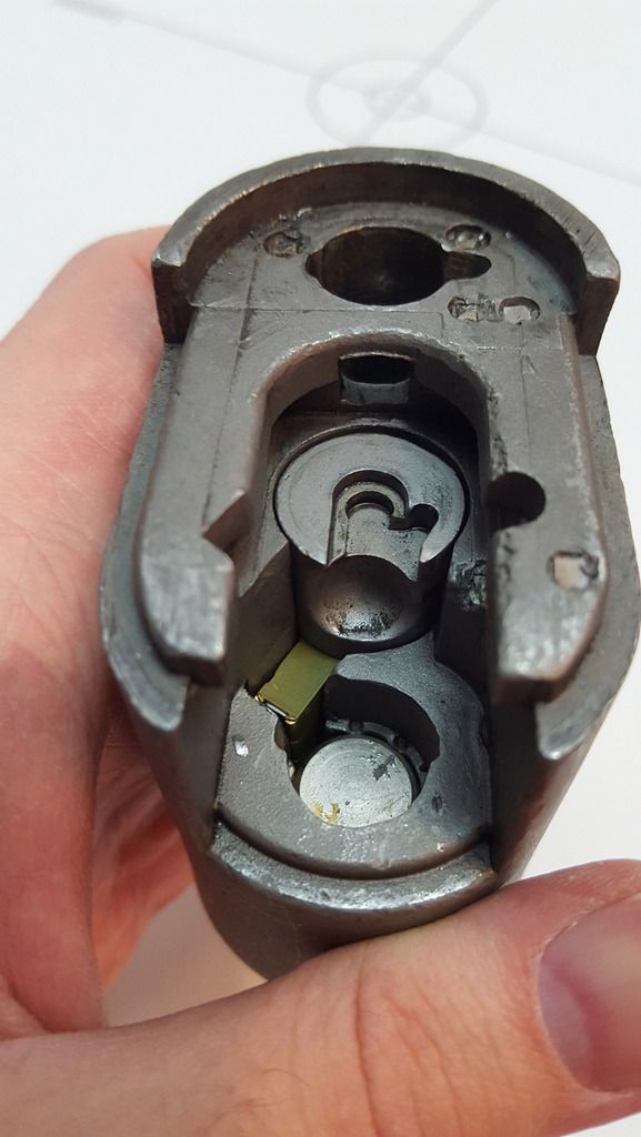
View inside the bottom half of the body. From front to back: first we see that large round silver looking disk recessed into the body. I believe that’s a continuation of the shackle, or at least a plug made from the same stuff, to deter drilling. Back one more component, that grey round plug with the odd notches cut into the top is the actuator that both locks/unlocks the lock, and changes the lock from open-only to control key mode. The notch cut into the top is exclusively for that latter purpose. At the very back is the shackle hole.

Image

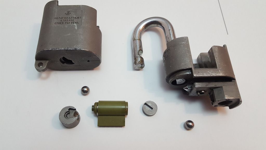
I’ve heard somewhere that military things should not strip down into more than seven basic components, as it’s easy for masses of parts to get lost. I’m not sure if this is true, but S&G military padlocks certainly strip down into less than 7 basic parts. Here we see the two body halves, the actuator (far left), the lock cylinder (green thing in the middle), two locking ball bearings and an anti-drill plate which sits in front of the cylinder:

Image

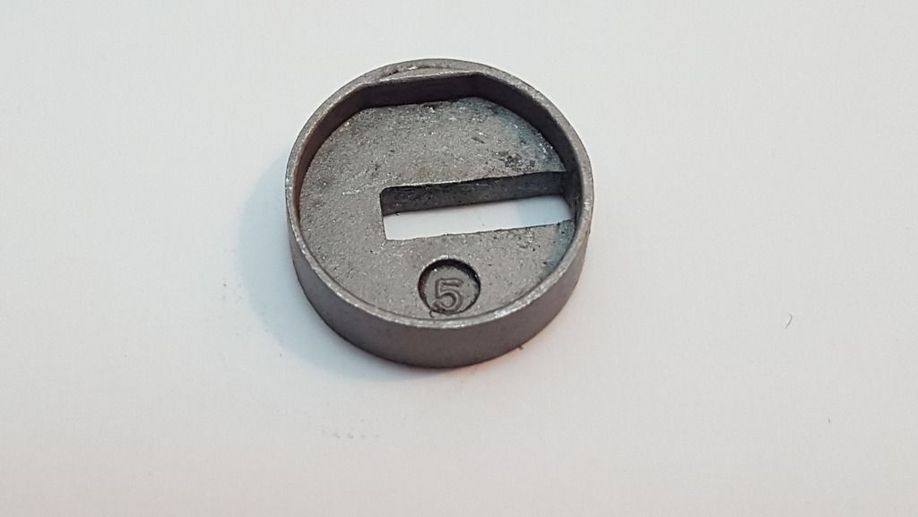
Here’s a closeup of that anti-drill plate. It has a small flat edge which fits with a complimentary edge on the cylinder, so that it sits correctly with the “mouth” over the keyhole. It also has a number stamped into it – in this case, “5” – which can be anywhere from 1-0. The purpose of this, and other UIDs stamped into the lock body, is to prevent surreptitious entry where a destructive attack is made on the lock, the pins decoded and then an identical and identically-pinned lock is made after getting keys cut or accessing the stock/secrets/whatever that the lock protects. The attacker will not only have to replace the lock, but figure out the correct number for the parts that were destroyed and replace the lock with identically numbered parts. A nifty solution to such a concern!

Image

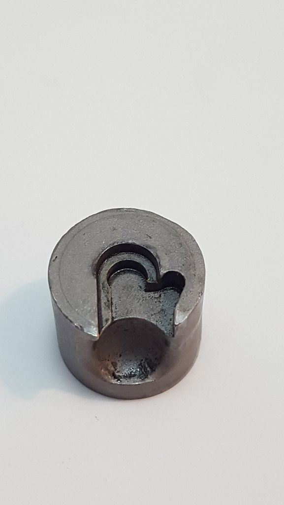
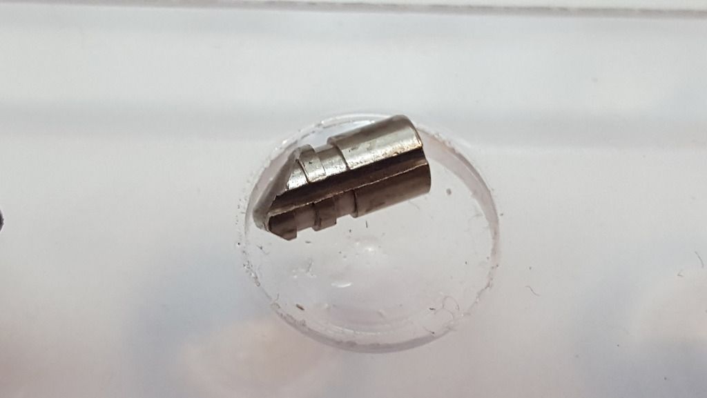
Here’s a closeup of the actuator. It’s a bit grubby at the moment! The cutouts in the top match a pin which sits proud on the top half of the body – when the key is turned to the control position, the pin is able to slide out of this cutout and the lock can be taken apart. The bit hole lower down is for a BB to sit.

Image

Underside of the actuator. The little nub fits into a notch on the cylinder to hold it in place. Note that this part also has a unique number – “2” in this case.

Image

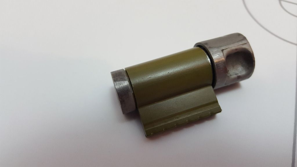
The cylinder! This is a Medeco Military cylinder (AFAIK the cylinders in green Teflon are military and the non-green (I believe brass) ones are civilian – however there exceptions to the rule, especially the older generation of S&G locks which tended to have brass Medeco cylinders regardless. This may have something to do with the newer ones being Biaxial, but I have yet to figure out the specifics):

Image

The back of the cylinder. You can see the notch which fits with the nub on the actuator, and it also a convenient fitting point for the C-clip nub:

Image

Let’s strip the cylinder!

Image

Closeup of the plug:

Image

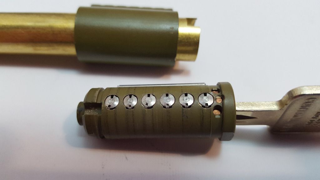
First off, note the three brass-looking anti-drill pins near the front / key entry point of the plug. Next, you might notice something odd about the pins, if you aren’t familiar with Medeco pins – they have little holes in. This is to do with the extra layer of security that Medeco locks provide – we’ll look at the specific parts as we go along, but in short, they have a sidebar (a metal rod with nubs sticking out of it) which slots into the side of the cylinder and prevents the rotation of the plug if it’s sticking out. The pins each have a notch cut into the side, and then all the pins are rotated to the correct angle, the nubs in the sidebar can slot smoothly into the side of the pins, the sidebar retracts, and the plug can turn. To rotate the pins, the pins themselves are actually wedge shaped and will sit at a certain angle in the angled cuts on the key. What looks like another cut in the pin, on the opposite side, is a little nub that keeps the pins within a certain degree of rotation – you can see that in the pic above, where there is a long-ish cutout around the bottom of each pin chamber, into which the nub is situated somewhere along that slot.

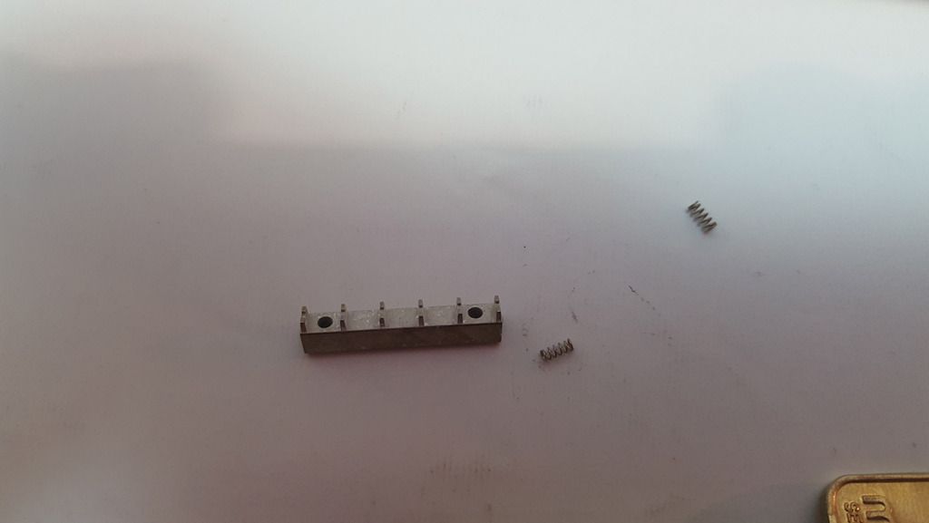
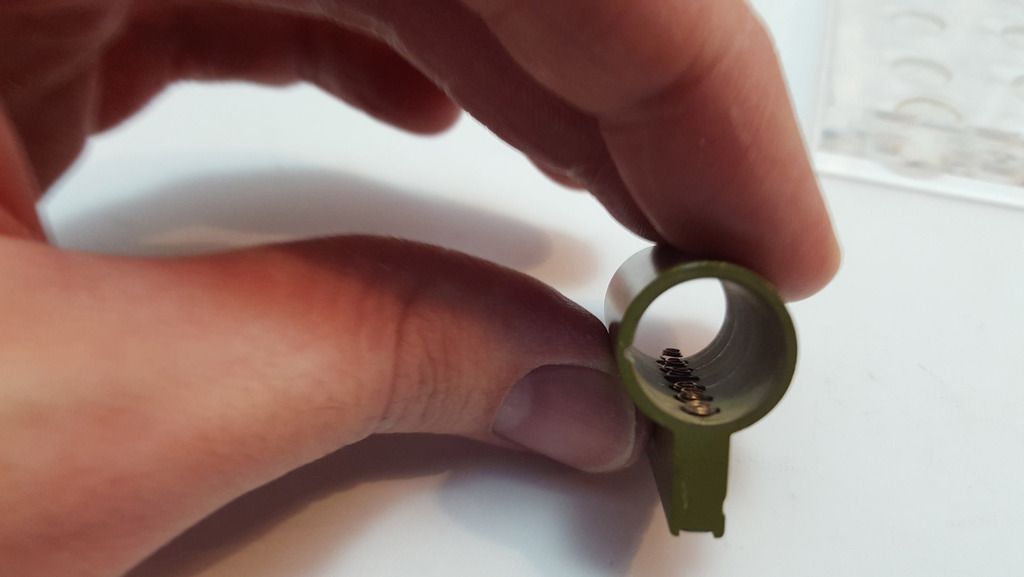
In the next photo you can see the sidebar. Note the six “legs” which stick into the side of the pins as previously described. The two small springs sit into the two holes and push back on the sidebar when it’s in the side of the plug:

Image

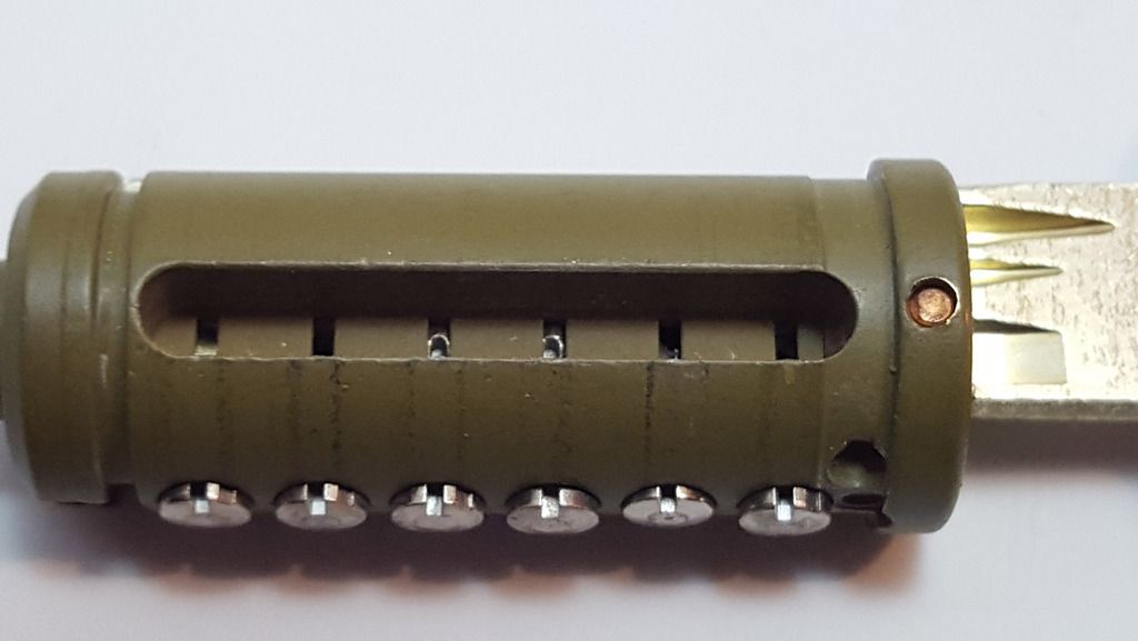
In the next pic, you can see the cutout made in the side of the plug for the sidebar. Note the six little slots made deeper into the sidebar cutout, where the sidebar legs go through and, when the key is inserted correctly, can sit into the slots in the side of the pins. Note also the anti-drill pin on the side near the key, too. Be careful when stripping one of these locks – the added dimension of a spring-loaded sidebar on the side of the cylinder as well as the key pins, whilst taking care of getting the plug follower in at the right angle can lead to a pinsplosion disaster :D.

Image

Key pins stripped from the plug:

Image

Image

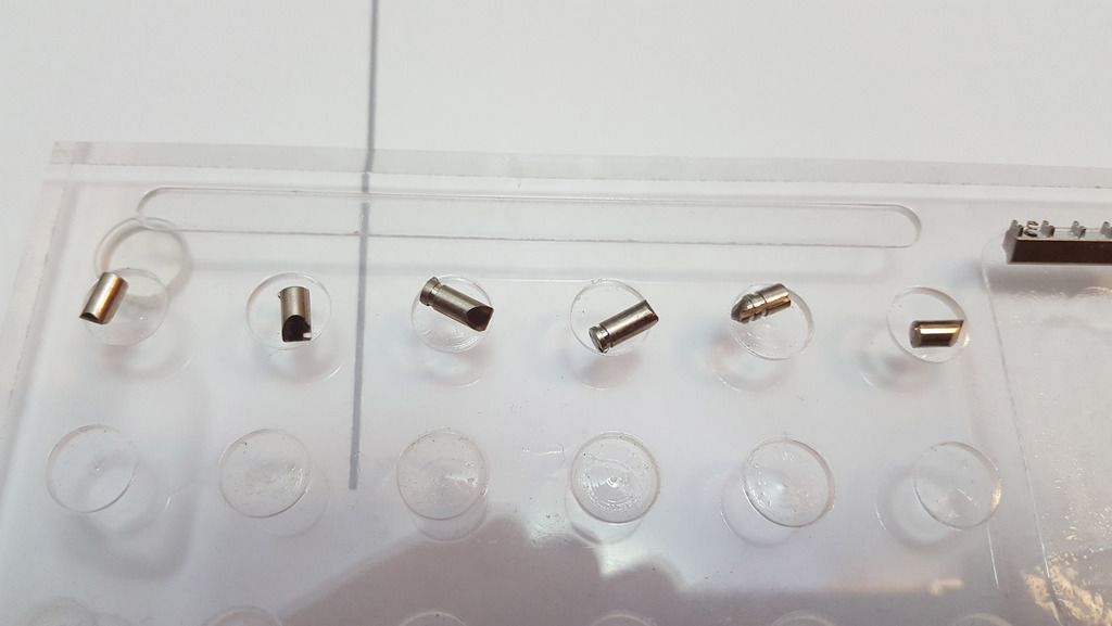
You can see the wedge-end on the pin that I was talking about – that will be rotated by, and sit flush in, the angled cut in the key. Sadly in this photoset I didn’t take a photo of that. You can also see some serrations – I assume to catch on the plug as an anti-picking measure (similar to a serrated pin), and the groove cut into the side for the sidebar to fit into.

Pin from the end, showing the sidebar cut, a “false gate” higher up (to fool picking/rotating attempts), and the keep-position nub on the opposite side and end of the pin:

Image

A look down inside the hollow cylinder with the springs sticking out of the bible:

Image

All key and driver pins. Interestingly, the drivers are all standard pins:

Image

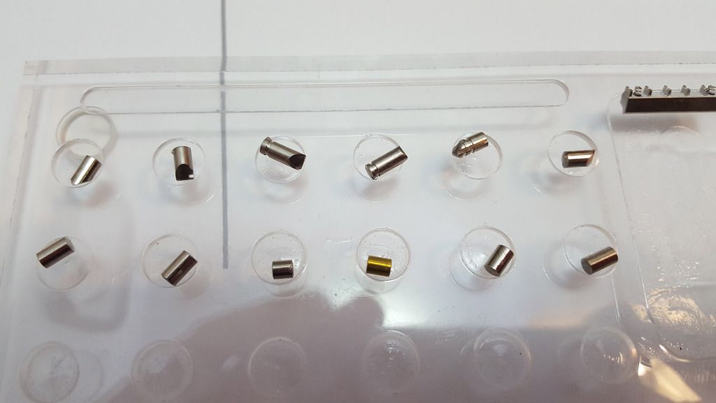
All the various lock bits and bobs:

Image

Fitting the anti-drill plate and actuator back onto the re-assembled cylinder:

Image

Slot it back into the lock, with the notch in the top of the actuator facing the gap in the body (important, as the other half of the body needs to slide in there!):

Image

Re-assembled:

Image

And there we go! I hope you enjoyed this little look at the Sargent & Greenleaf 833!

Image
PreviousNext

Return to Your Lock Collections

Who is online

Users browsing this forum: No registered users

Don't forget to visit our sponsors for all of your lockpicking needs!
Powered by phpBB © 2000, 2002, 2005, 2007 phpBB Grop
"CA Black" theme designed by stsoftware