So, it’s been a little while! But fear not, I have a cool update today.
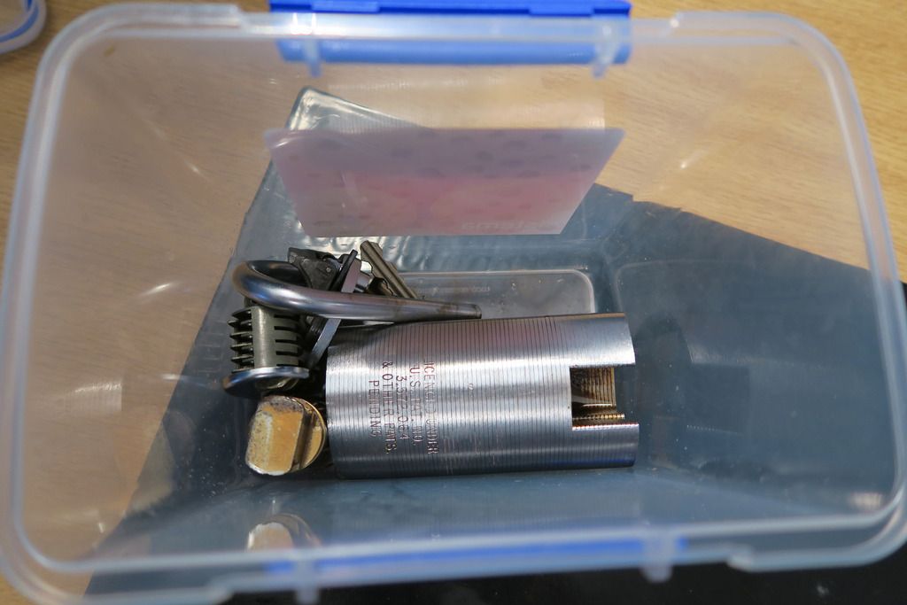
Mystery box:
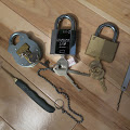
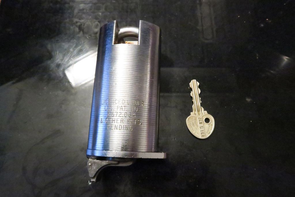
There she is!
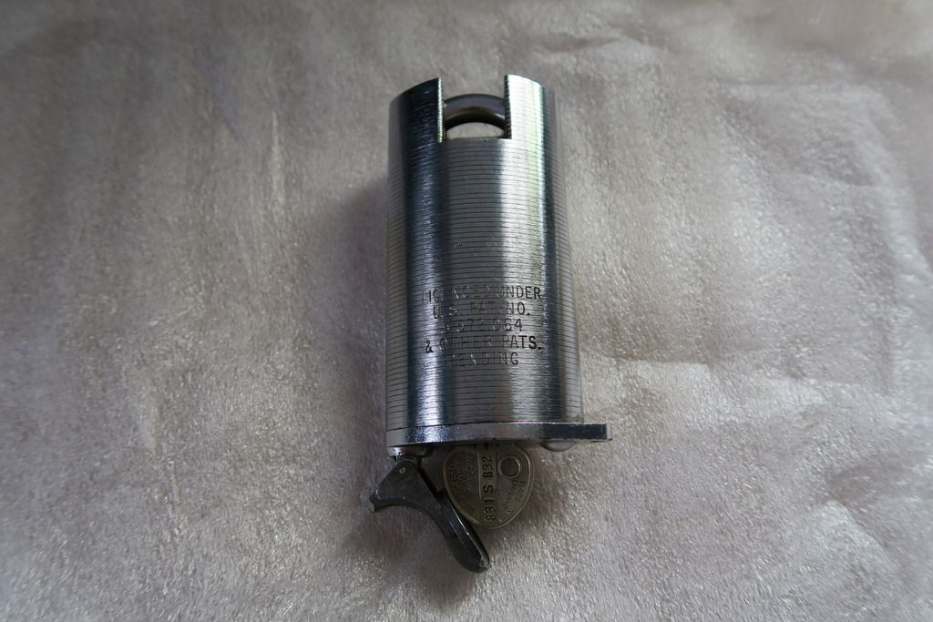
It’s an Ingersoll. It’s also an S&G. This is a really interesting lock and as soon as I saw it on eBay I had to have it – sadly the seller was asking crazy prices for it so I managed to convince him to accept about half what he wanted. Score!

Chronologically, this lock sits, I believe, between my other “Vintage Ingersoll” (the Sub Liquidonics / Miracle Lock one, which I now believe to be a Miracle lock body with an Ingersoll core), and my modern Ingersolls. It’s dated as 1973 (stamped on the body) so pretty old, but it has a few weird crossover things:
1. It’s branded with both Ingersoll AND Sargent & Greenleaf, strengthening my conclusion that they seem to have had a period of crossover / co-operation is lock design and manufacture as I’ve seen this before in both body style and branding – I’m not sure if Ingersoll agreed to make locks for S&G or vice versa, but this lock is actually branded with both companies which is very cool.
2. The body shape is very similar to the Sargent & Greenleaf 831, so there was clearly some design inspiration there in one direction or another, although of course this Ingersoll uses laminate plates.
3. The key bow has the same style / design as the older Ingersoll core that I have (“Vintage Ingersoll”), however the actual key profile itself is the wiggly, 10-lever version (same as on my new Ingersolls) rather than the squarer 8-lever version on my other old Ingersoll. In other words, the key is a hybrid between the two locks that I have so far.
4. Speaking of key designs, the key for this lock is stamped with the numbers “831 S 832”, as opposed to “021 L 036”. I’m not sure what the numbers/letters on the old one refer to (maybe 021 is the model number for that lock? Not sure what L would be though), but it seems more than a coincidence that the lock that looks very much like the S&G 831 also has 831 stamped on the key. Maybe “S” is for S&G? Does that mean there’s an S&G 832 out there too? My investigations create more questions than answers, sadly.
5. Whilst I’ve seen locks similar to this one elsewhere on the web, I’ve never seen one with this mechanical snap-close on the keyway area before
Anyway – enough hypothesizing for now, we’ll take a look at specific aspects as we strip the lock down. Note: This is going to be a LONG post with a lot of photos as I totally stripped the lock, including the cylinder and cleaned it all up – there’s also a lot of things I want to point out for this one. Let’s get started!
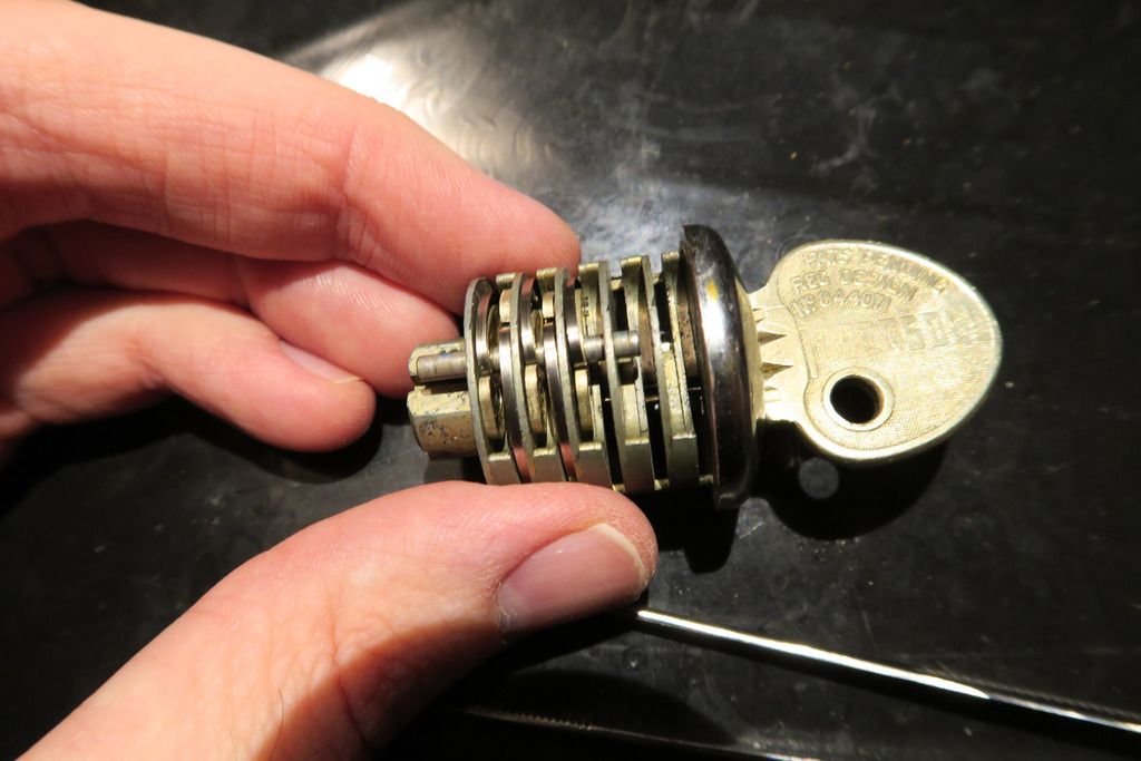
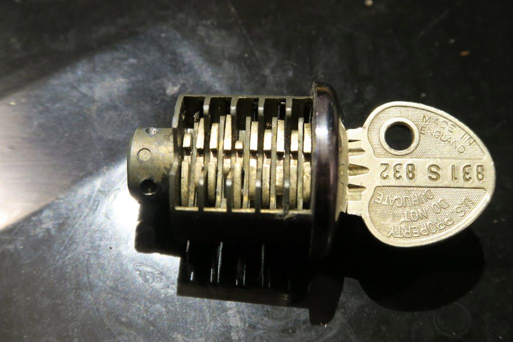
Here’s the aforementioned key:
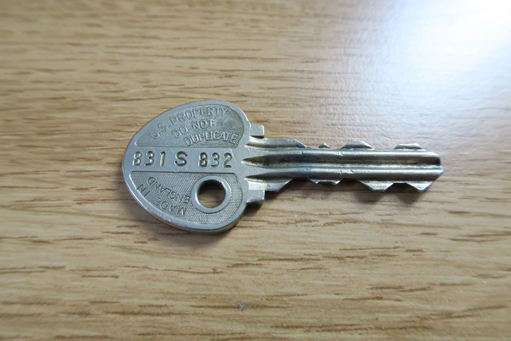
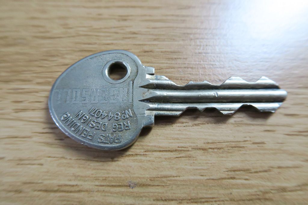
If you check over my old Ingersoll posts, you can see that the bow shares a strong resemblance with the “Vintage Ingersoll” lock rather than the modern ones, however the key profile is clearly the modern design. Also note the stamped numbering (831 S 832). Mysterious!
Body “Back”. I do love the say the laminate plates look on these Ingersolls:
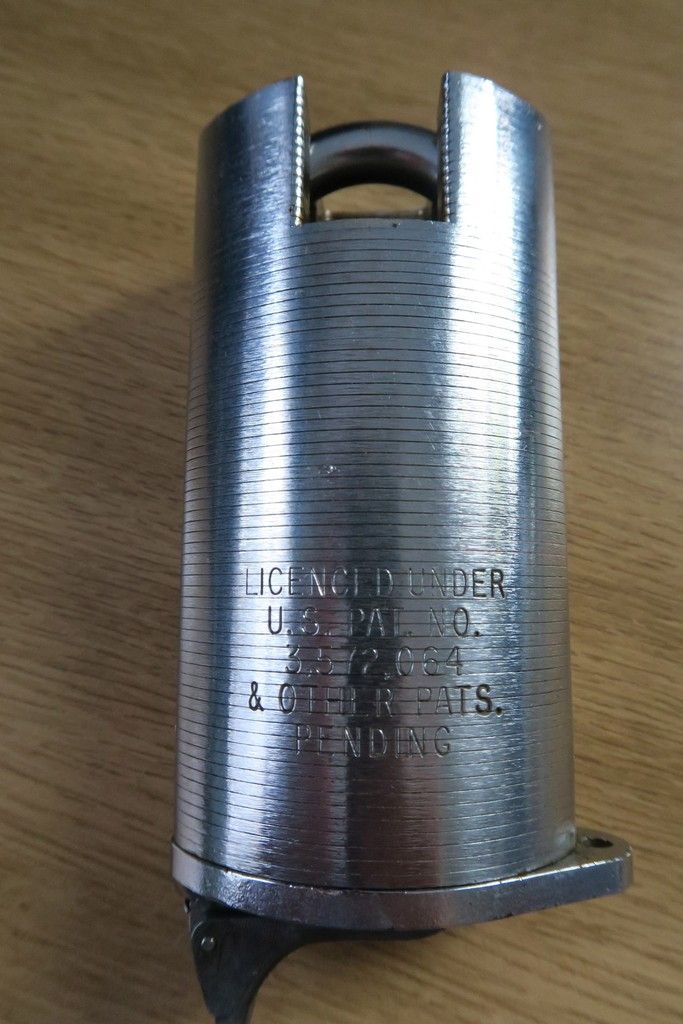
Close up of the Patent stamp:
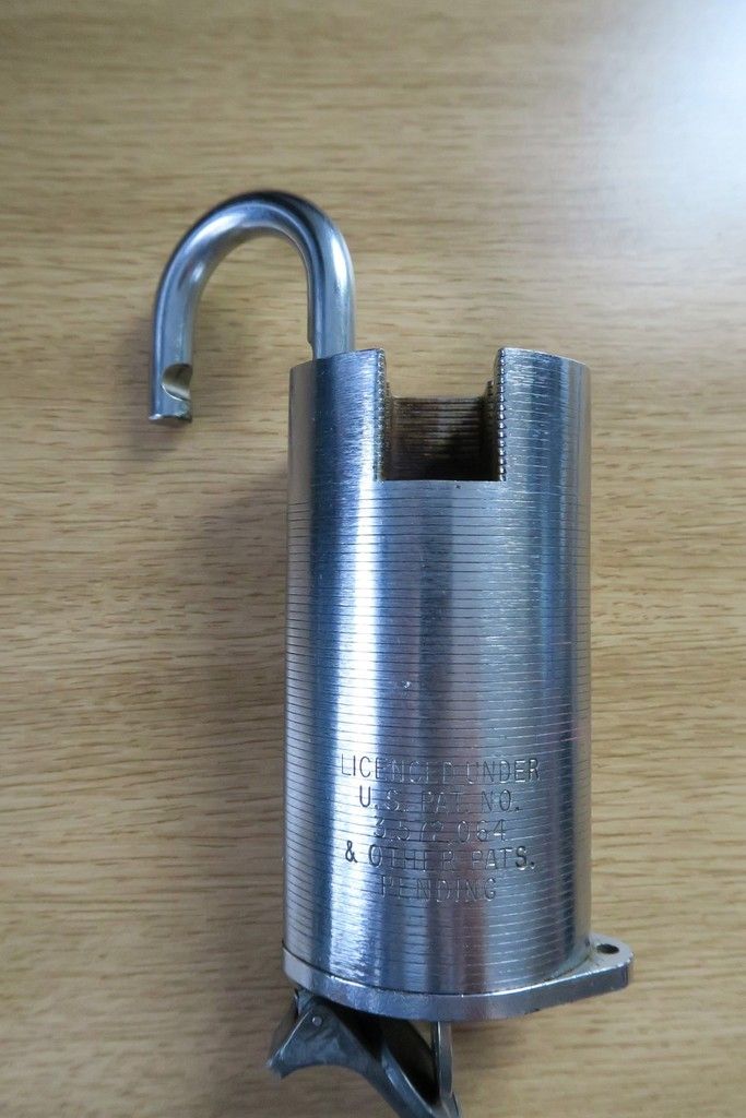
Body “Front”. Note that the way the extra-closed shackle housing looks is very similar to the modern Ingersolls, and yet the overall body shape is reminiscent of the S&G 831:
Closeup of the front text:
Note both the Ingersoll and S&G marks, as well as the US stamp (indicating a gov’t or military lock) as well as the date – 1973.
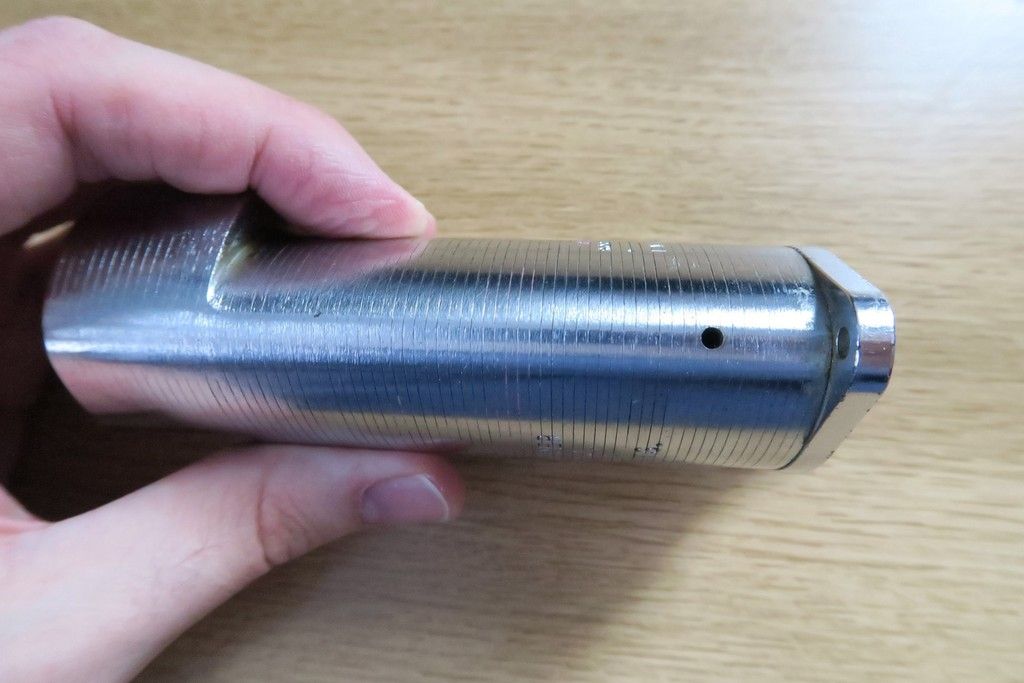
Bottom of the lock:
The bulge on the right obviously hides the fixing screw which will be accessed from inside the shackle hole, holding the bottom plate on. The odd snap-closed (I assume weather resistant?) catch is on the other side, I assume with another screw behind that holding the bottom plate on. Note also that the right hand side sticks out and has a hole, allowing a chain to be attached.
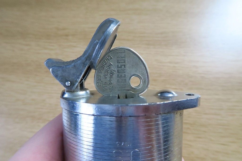
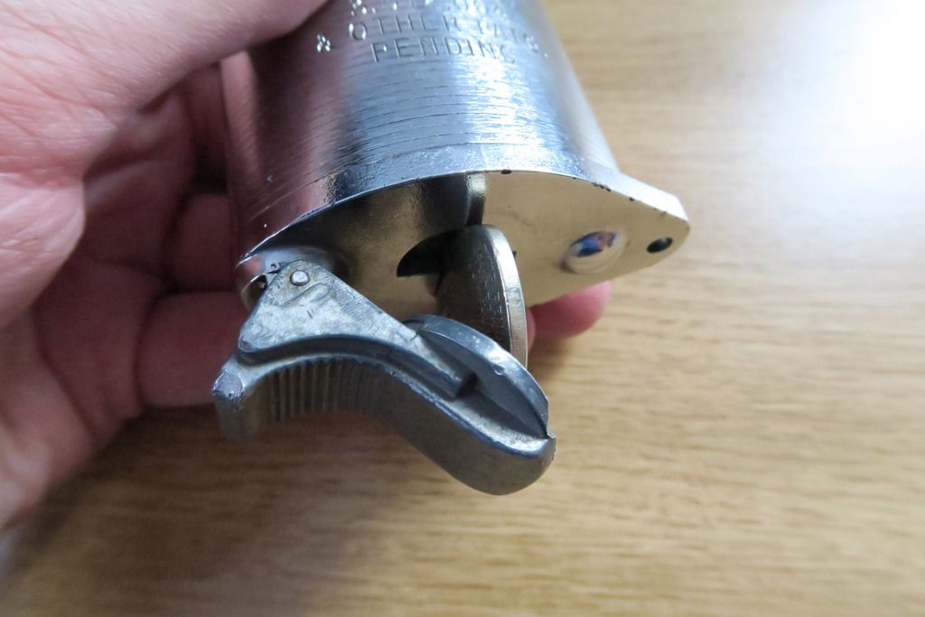
Side on shot of the snap close:
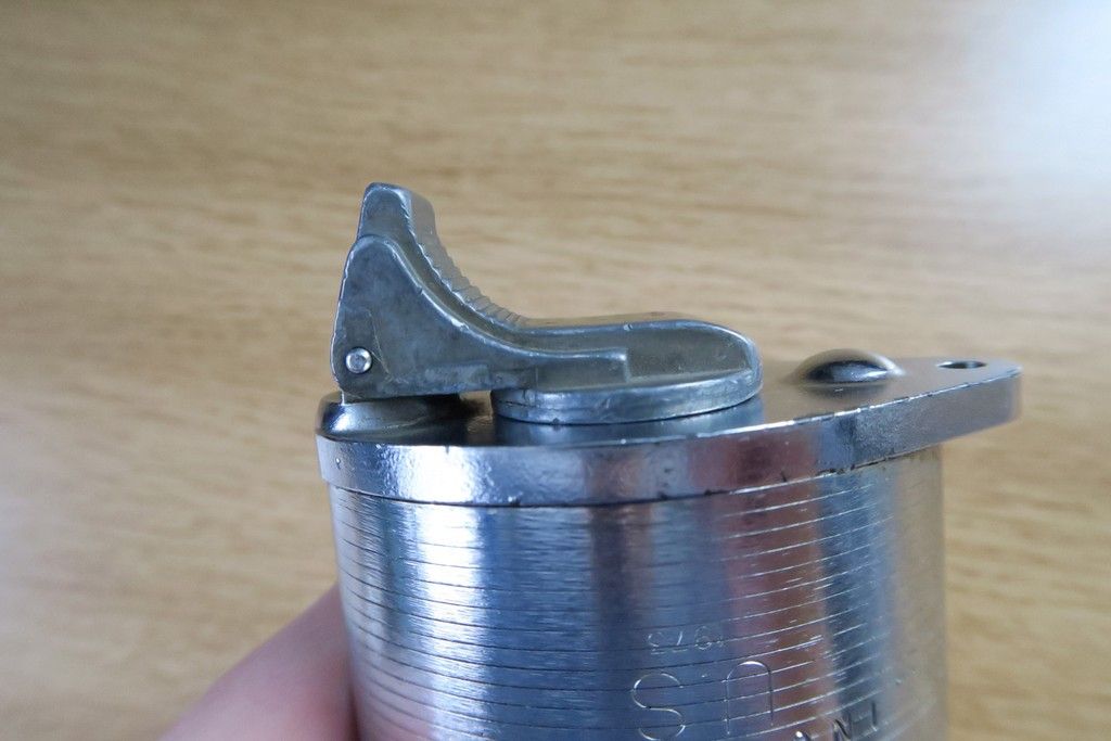
It’s operation is simple – it’s under spring tension, and pulling back on the serrated left side of the rocker allows the whole thing to hinge back and left, exposing the key hole. When I saw this on eBay I assumed that the round, flat closing plate which actually covers the keyway is magnetic, however that is not the case – it’s held down purely with spring tension.
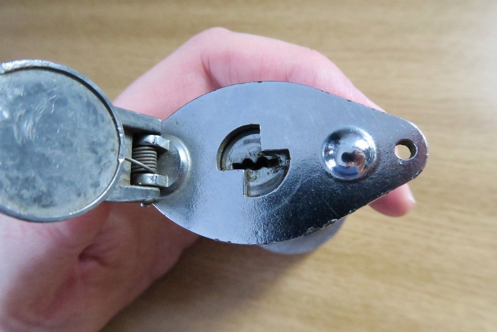
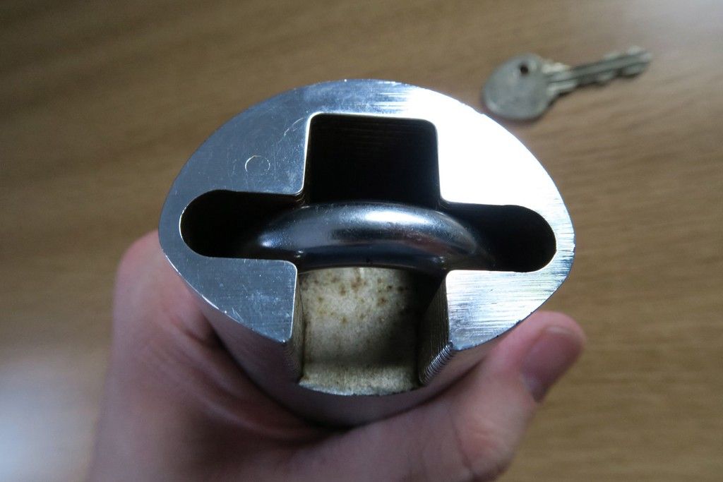
Snap close pulled back to reveal its own operation as well as the keyway. Note that it’s the more modern Ingersoll design (not sure if the Ingersoll keyways have a specific name or code designation?):
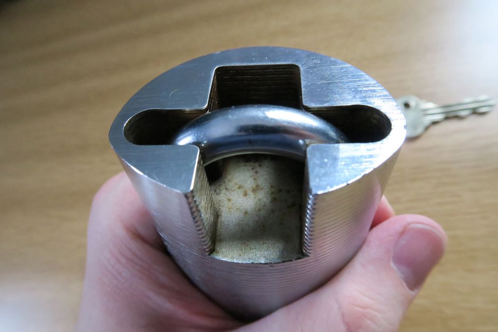
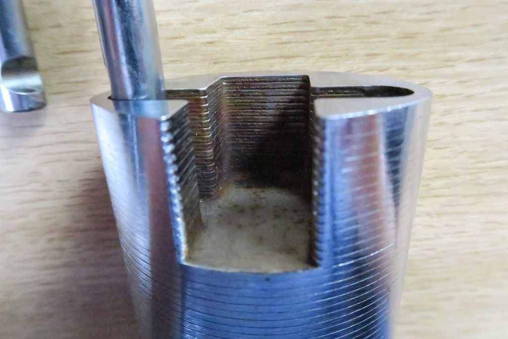
While we’re down here, let’s have a look at the underside of the top portion of the body that provides the extra-closed functionality:
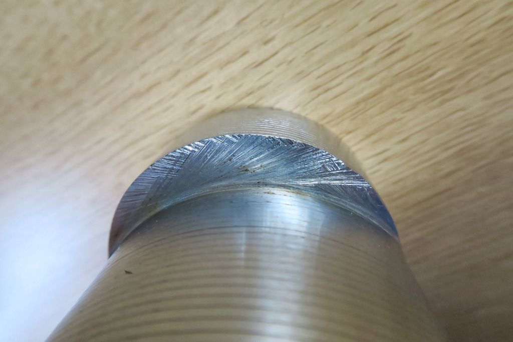
Interesting cutting marks on that metal. Seems like maybe those upper portions are cut from a long tube and then welded on?
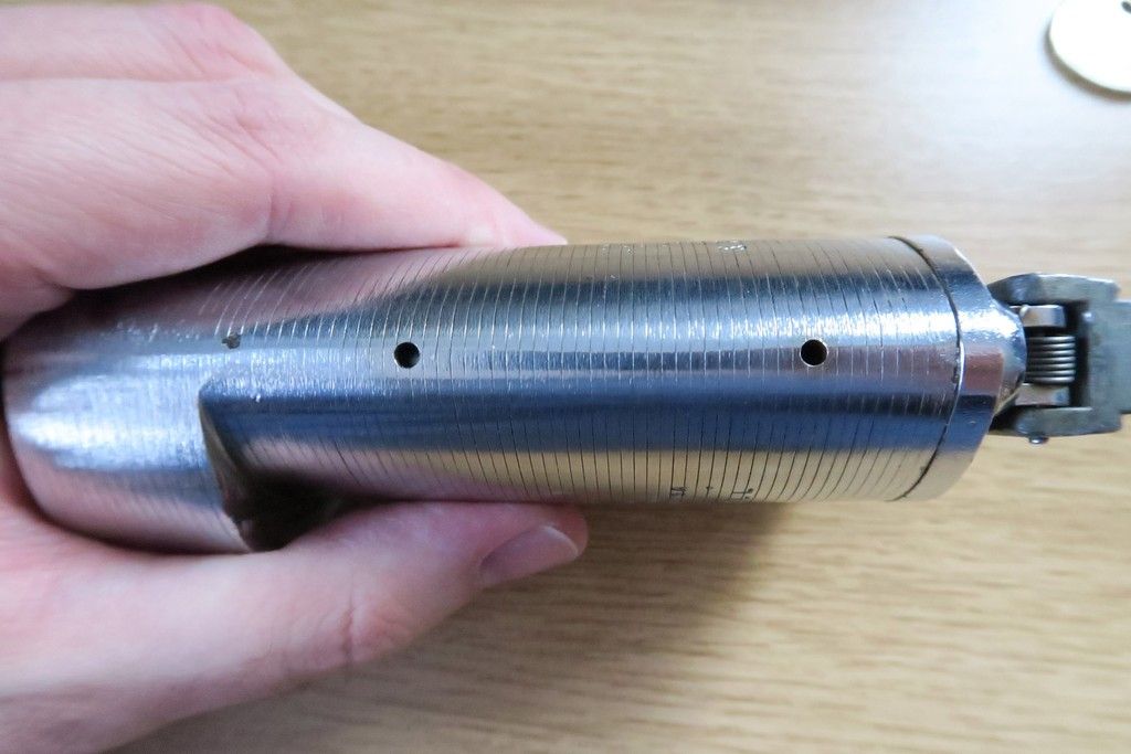
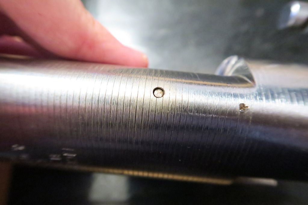
One side of the lock, showing what looks like two drain holes. This will be important soon!
The other side, with only one drain hole:
Top of the lock:
The style here looks very much like the modern Ingersoll extra-closed, in fact I’d say that there’s little to no difference there. There are –some- similarities to the S&G 831, but honestly I’d attribute that more to just being how extra-closed shackle locks must work rather than anything else.
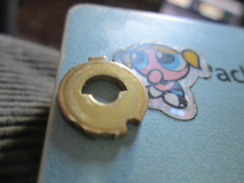
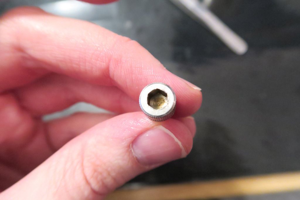
Note that little round divot thingy there:
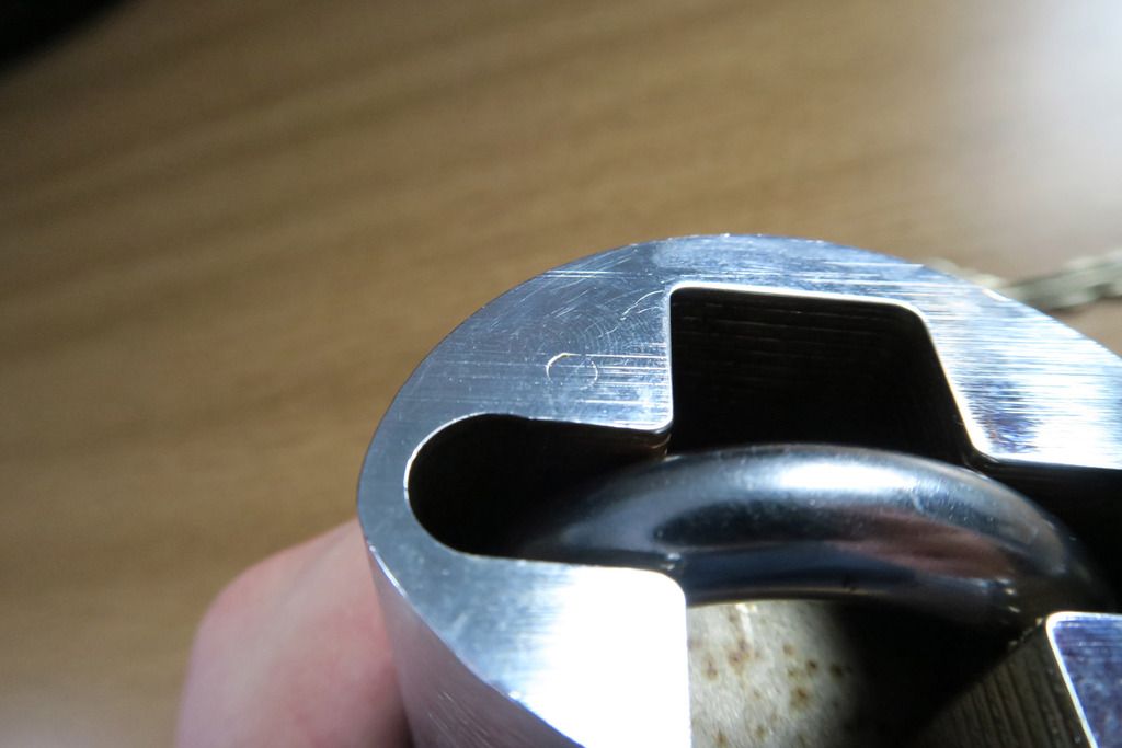
I’m not sure if this is a rod that has been pushed in after assembling something or just an artefact from production? Interesting.
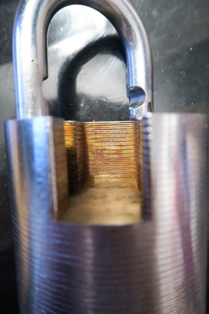
Another shot to point out some of the rust that seems to be forming inside the upper shackle protecting area. Hopefully I can find a way to remove this! I like that the edges of all the plates are rounded, too:
Snap-close pulled back and key fully inserted (locked position):
Key rotated to unlocked position:
Unlocked:
Note that despite being an extra-closed shackle padlock, and despite both the “Vintage Ingersoll” and modern XClosed that I have being removable shackle padlocks, this one is actually not removable shackle – kinda. We’ll get to that!
A better look at that rust inside:
Yeesh!
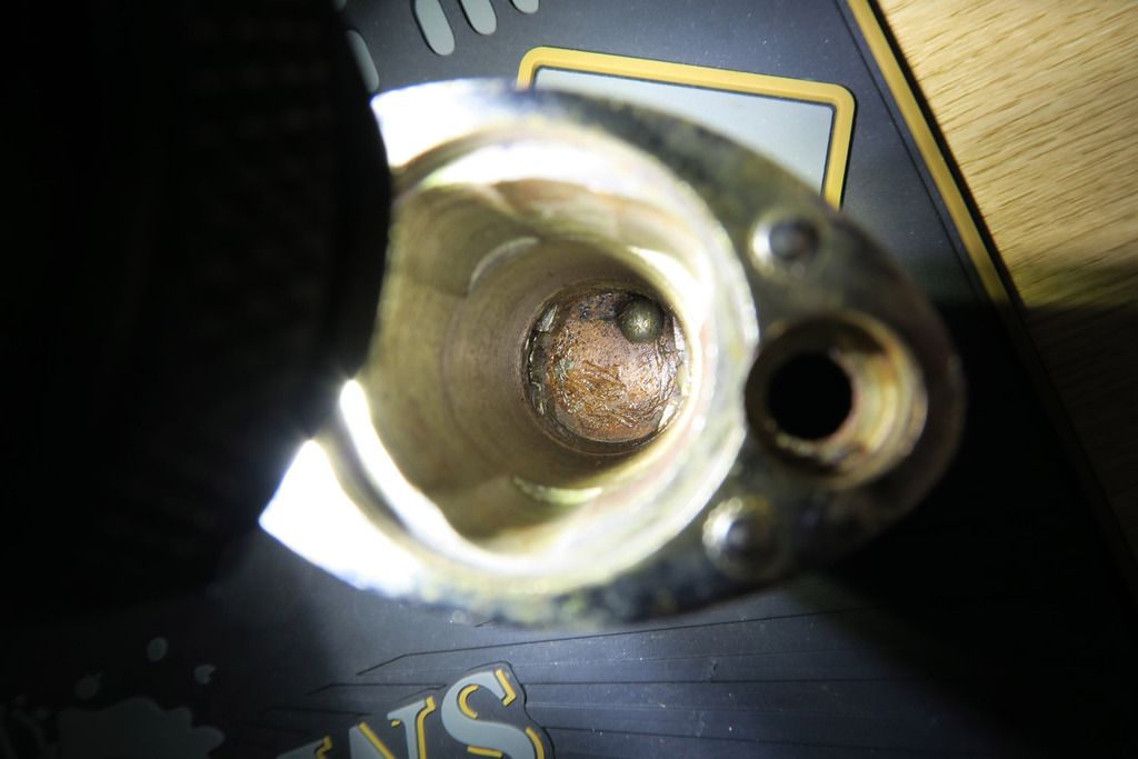
So, time for a breakdown! After shining a light down inside the open shackle hole, I could see that the (I assume) screw at the bottom is severely rusted up, so much that it’s really hard to even see what kind of screw it is. I spent ages fiddling with various hex screwdrivers, as the slot looked very much like a hex, to no avail. I tested some Torx which didn’t seem to work and went back to hex... After quite a while I eventually found that the screws are indeed Torx, size ‘30’. The star edges were so filled up with rust and grime that the nut looked (and acted) like a hex hole instead!
So, with one screw removed, I turn my attention to the other side. The bottom plate clearly isn’t coming off or rotating, and from my other Ingersolls I know that they usually have a screw on both sides. On the XClosed versions usually the shackle comes out completely, but the closed and open versions do not, and in those cases a roll pin is hammered in from the side perpendicular to the shackle. So I start looking for a roll pin / set screw but the body is totally smooth.. Except for those drain holes. Well the bottom drain holes are too far from the shackle so those can’t be it, so I started testing inserting very small screwdrivers – hex, flat, torx – into the upper hole, with no effect. I assume it’s rusted up?
So I keep testing and digging, hampered by the fact that the holes are so tiny, I can’t fit most of my tools – even my smallest tools – inside. Also due to the small hole and lack of other places that connect to this side of the shackle hole, it was nearly impossible to shine a light inside. When I DID manage to get a light in, it looked like a flat head screw? Turns out that’s probably just the laminated plates of the body on the other side of the hole. I looked all over the body again, tried rotating the shackle and bottom plate, nothing.
Strange – these kind of locks are usually disassemblable, right? So I started playing with the shackle, turning it around and seeing where it popped up and where it was held low. Clearly it was being held into the body with
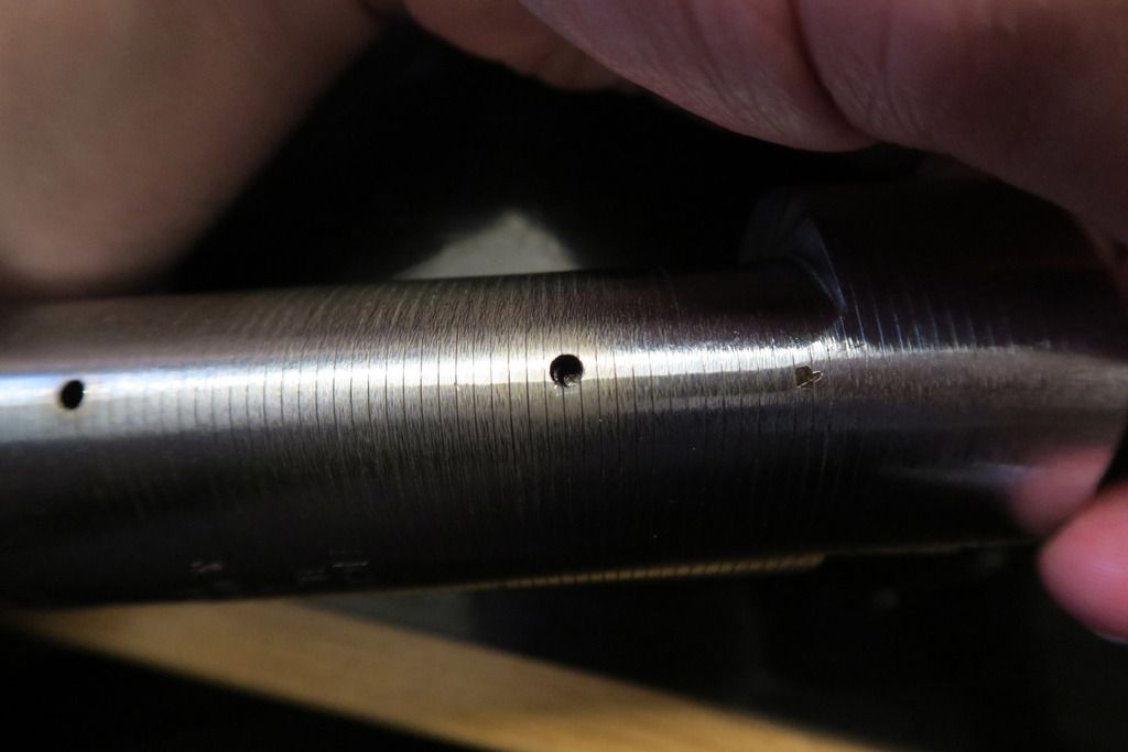
something. Through the upper hole, while it’s nearly impossible to see inside when the shackle is clear, when the shackle is lowered you can see the outside of the shackle quite easily because it’s so much closer to the small hole. So I started examining the shackle from the outside, turning and raising/lowering it slowly to try and observe where the cut-out areas are and how the bottom is held on – I was looking for a low cutout and then a sharp return to the regular thickness, to catch on something to stop the shackle coming out. What I found instead was... Strange:
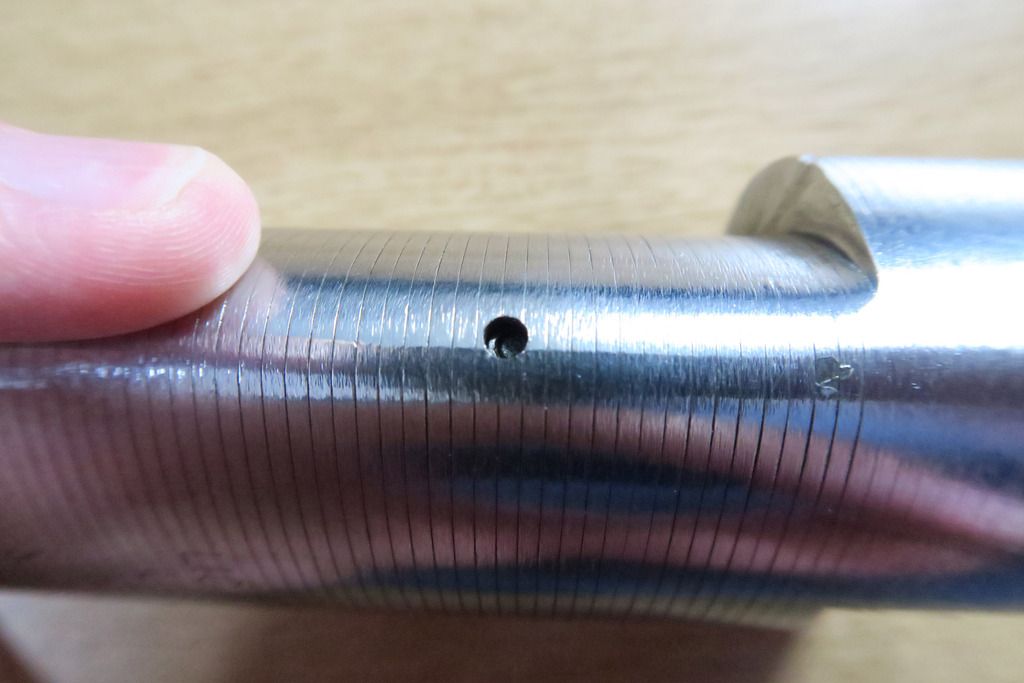
It’s kinda hard to tell in the photo of there are two points at the bottom of the shackle where a small dip/divot exists... Is it a grub screw? Unsure, I started putting screwdrivers and such into the shackle, also rotating it around to see what was going on. Recessed on one side, sticking out on the other...
And then it hit me.
It’s a
pin.
I took me pin punch, flipped the shackle around and hammered it back into the shackle, clearing the obstruction and sliding the shackle up...
Boom.
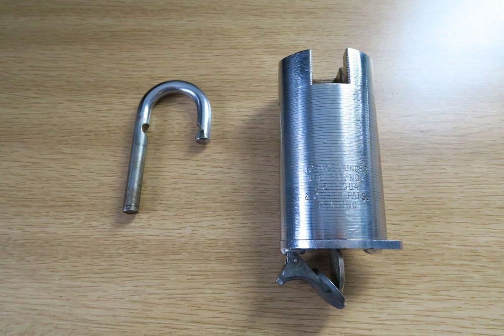
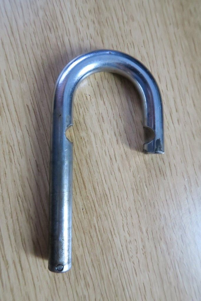
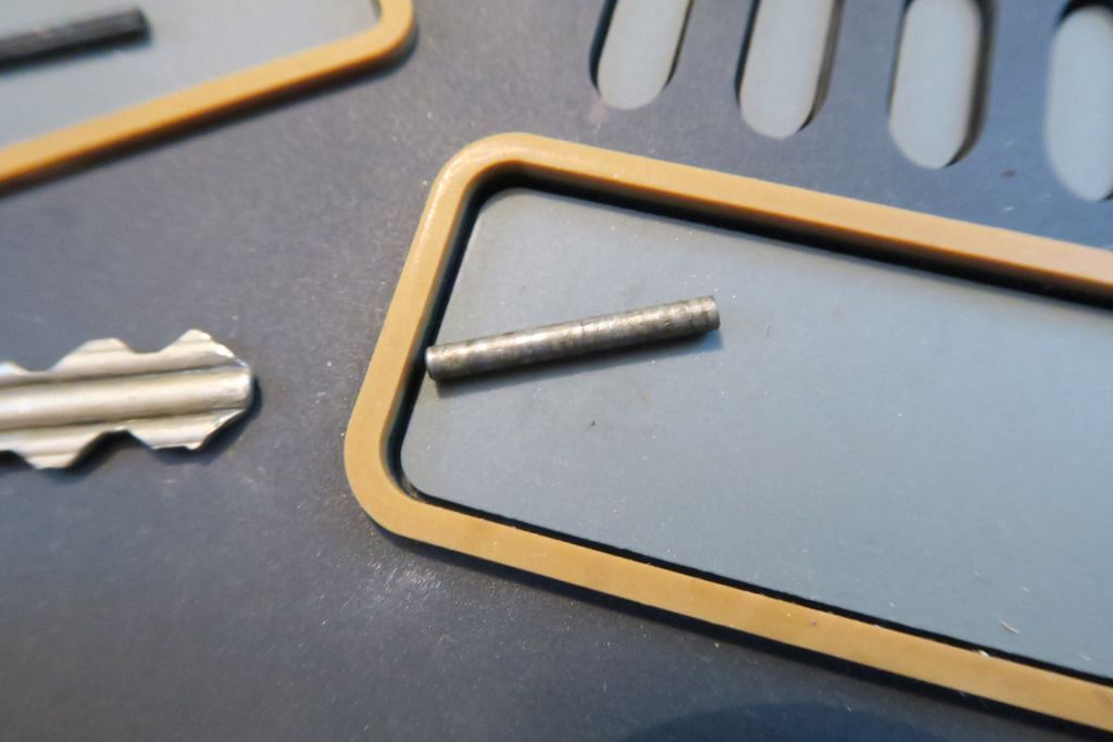
There’s the shackle:
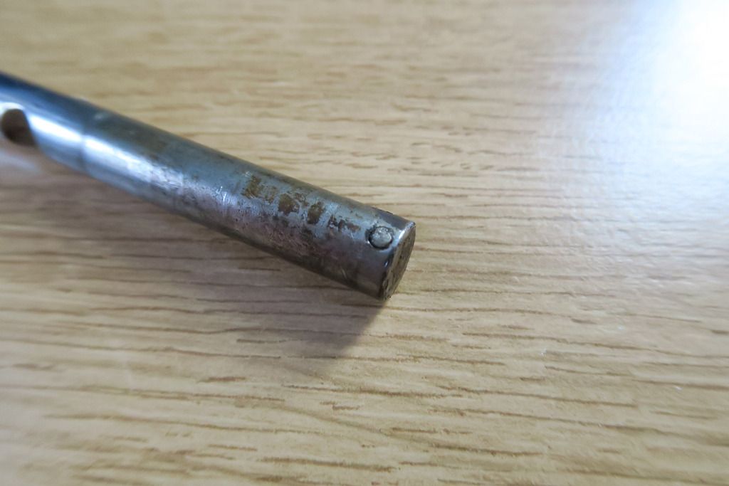
And there’s that pin:
Well,
that was an exercise in frustration! But overall, I’m glad they decided to use some weird-ass esoteric fitting on this lock – it kept me on my toes and provided a fun puzzle. I’m glad I managed to figure it out by myself!
Essentially, the shackle has a kind of roll pin embedded into it. When you want to seal the shackle into the body, you just line up one edge with the upper hole in the outside of the body and use a pin punch or something similar to push the pin out a bit. It can’t come out all the way due to the width of the shackle hole but it’ll come out far enough to catch on something in the upper body, stopping the shackle from being removed. In this way it also allows you to use this as a shackle-retaining or removable shackle padlock. Cool stuff!
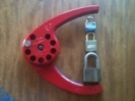
Moving on then! Let’s take a look at those two grimy screws that I mentioned earlier:
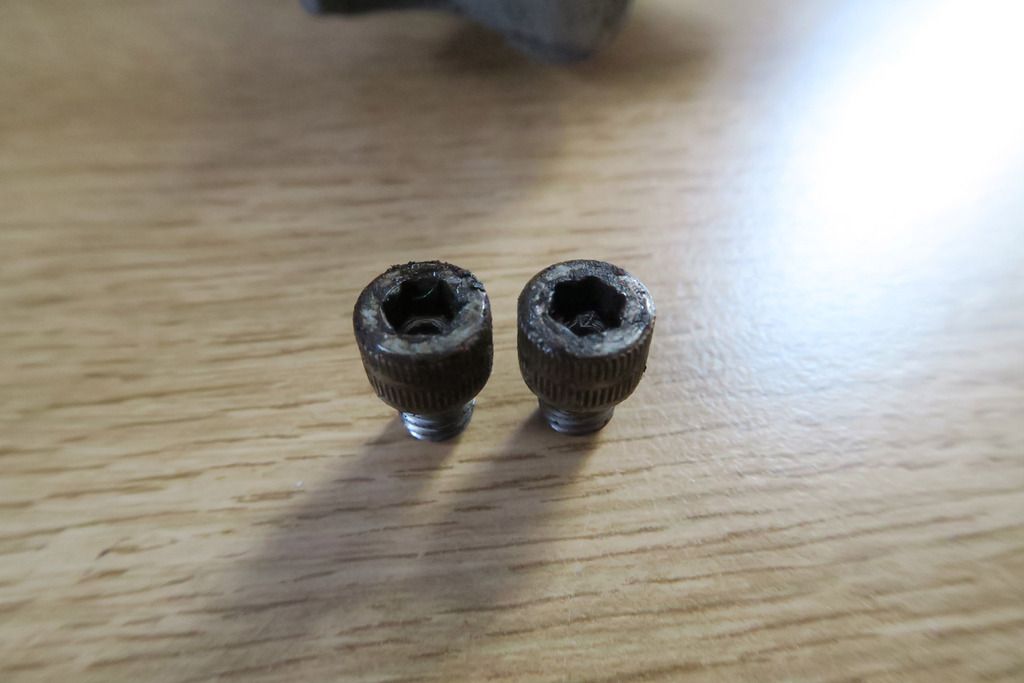
They’re so gummed up, they look like hex screws!
With those removed, we can now remove the bottom plate and the cylinder:
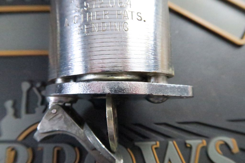
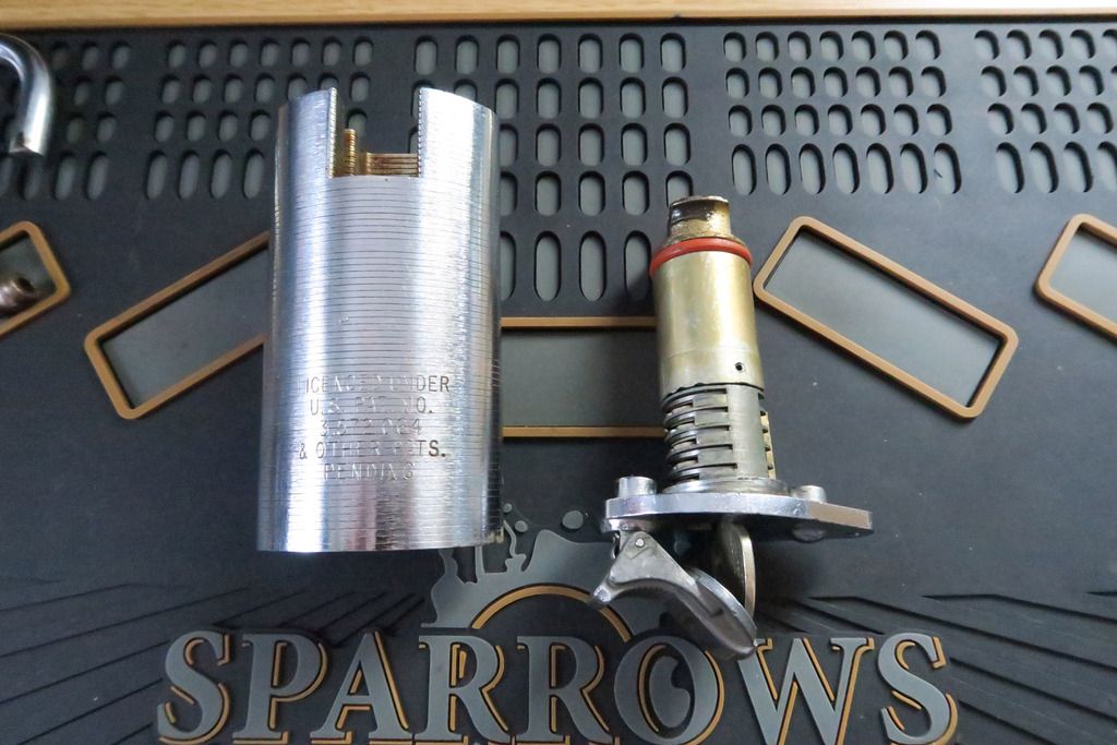
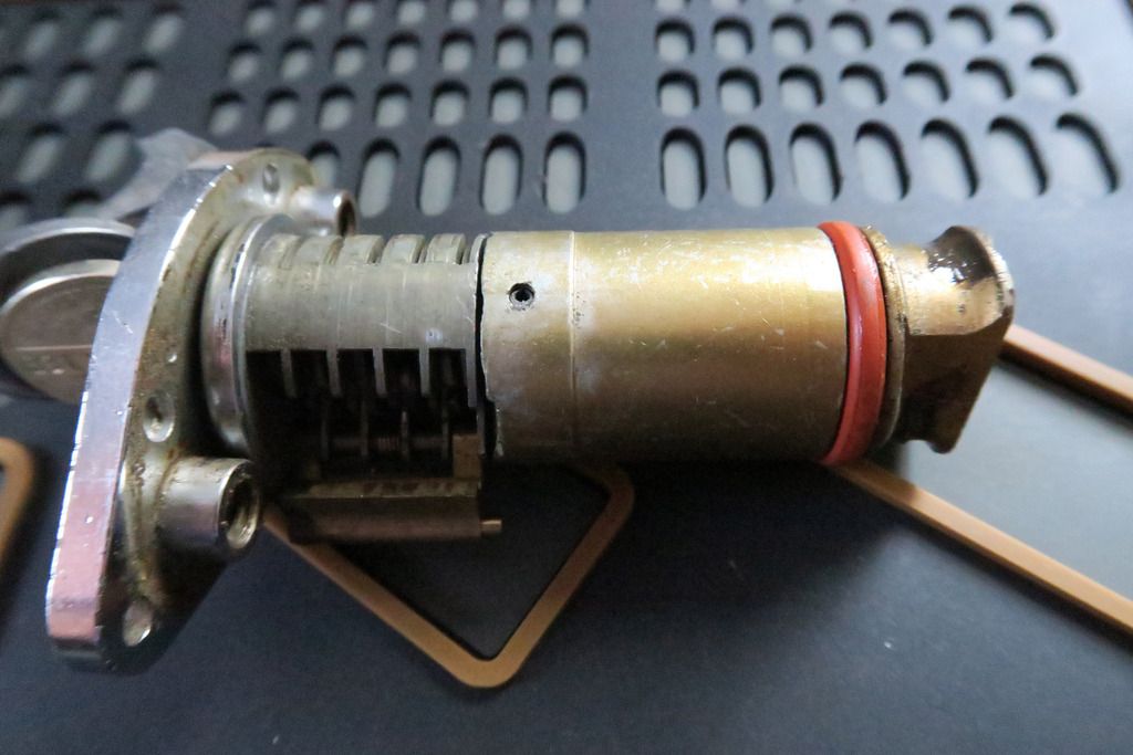
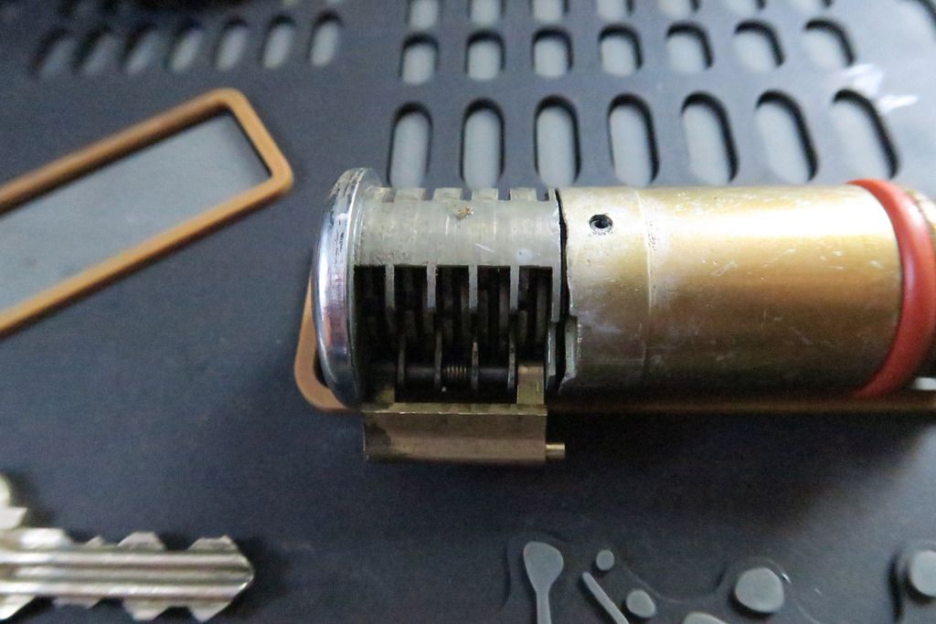
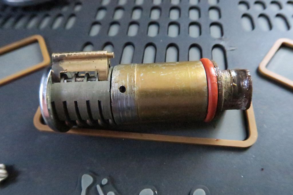
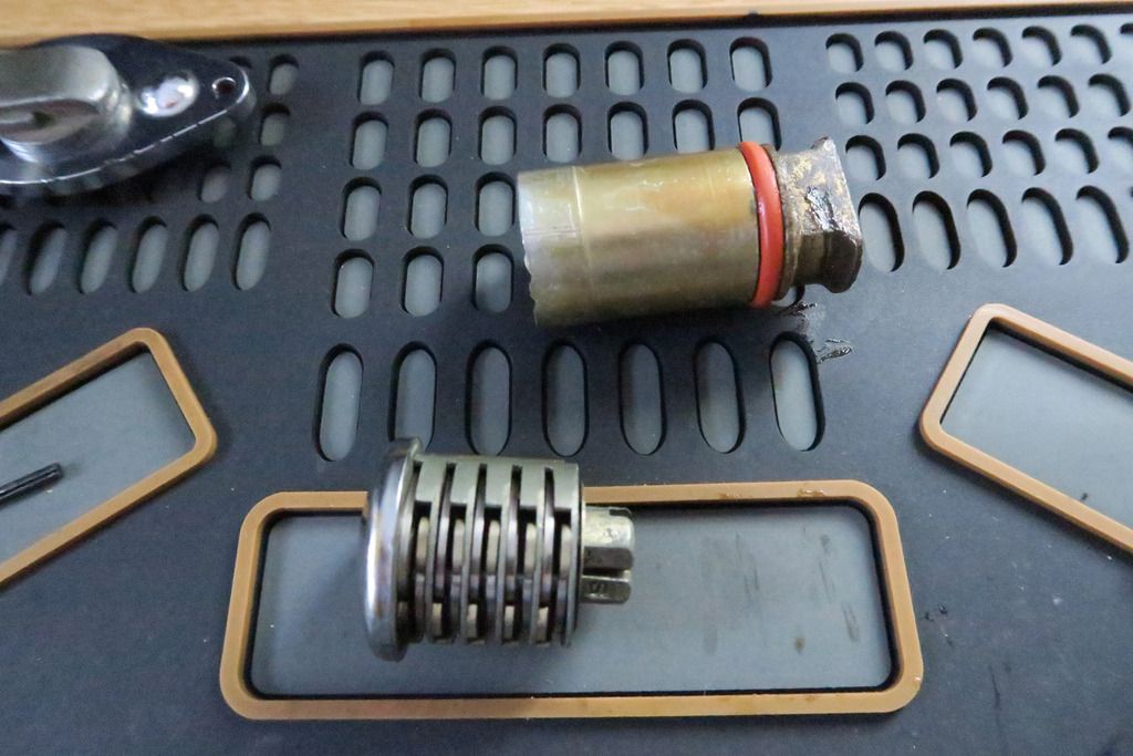
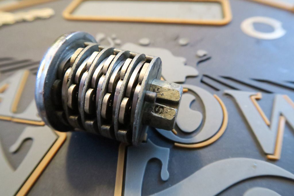
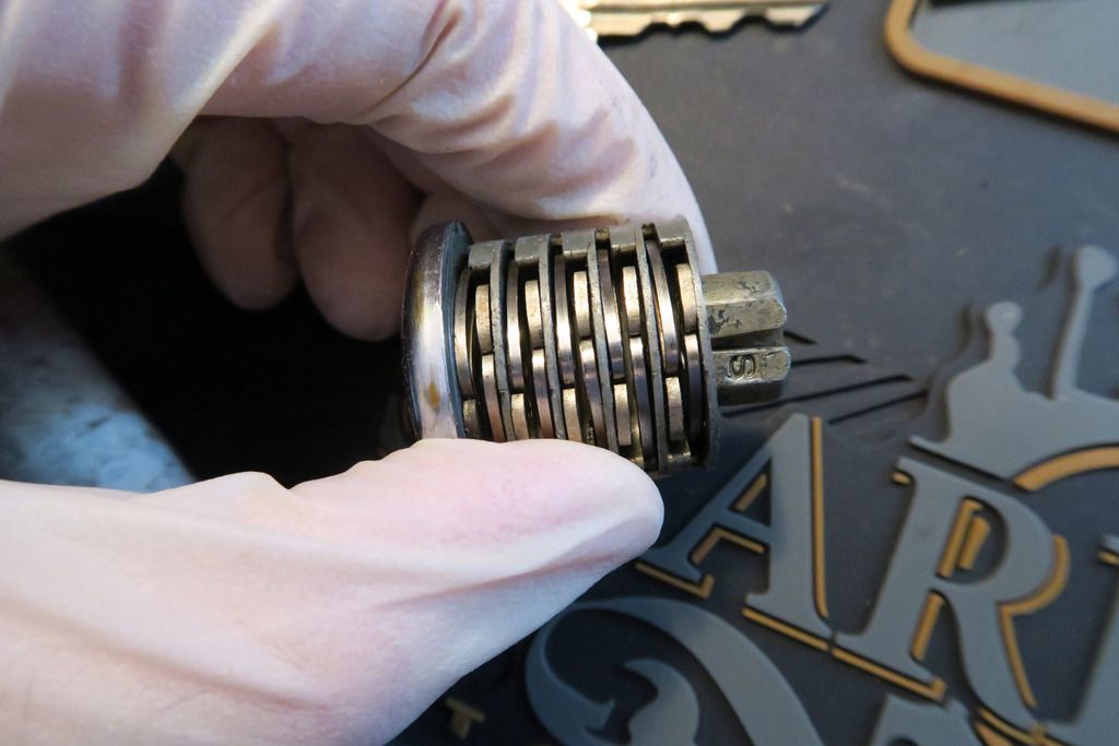
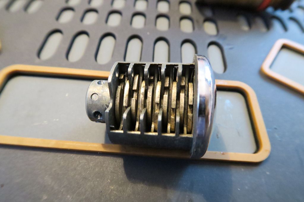
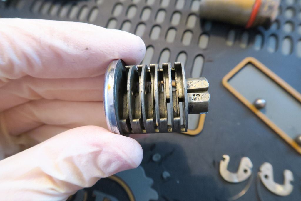
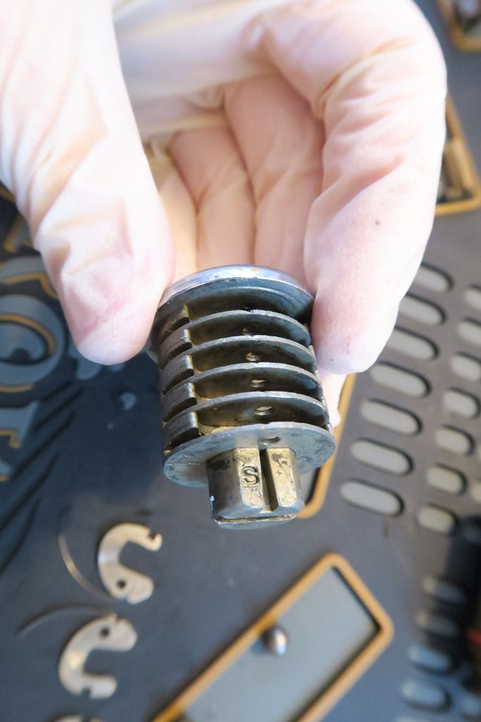
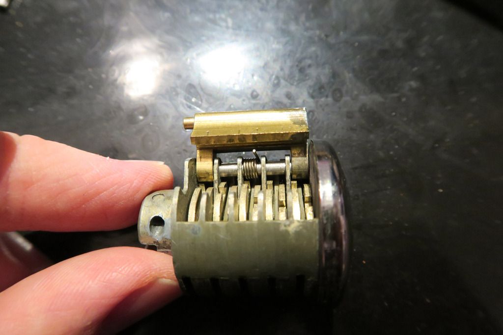
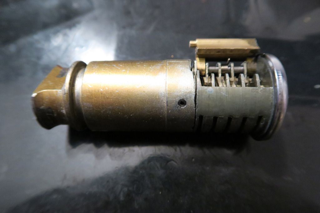
The cylinder and actuator are fixed together. Here’s the module next to the body:
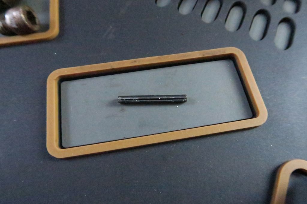
Here you can see the Ingersoll cylinder held to the brass tube with a roll pin, with the actuator at the bottom along with a rubber gasket presumable to keep water from flowing in from the upper part of the lock down into the cylinder:
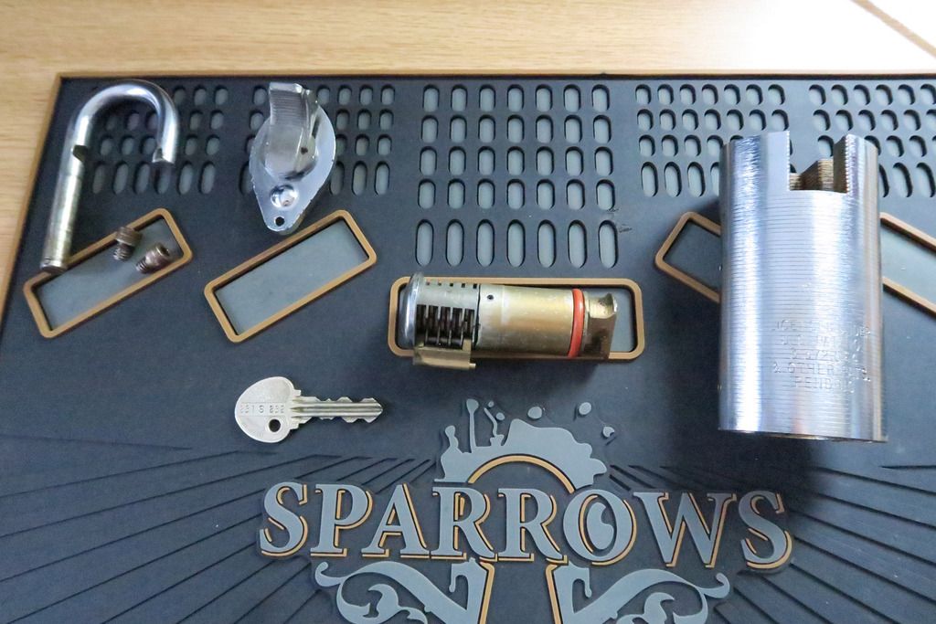
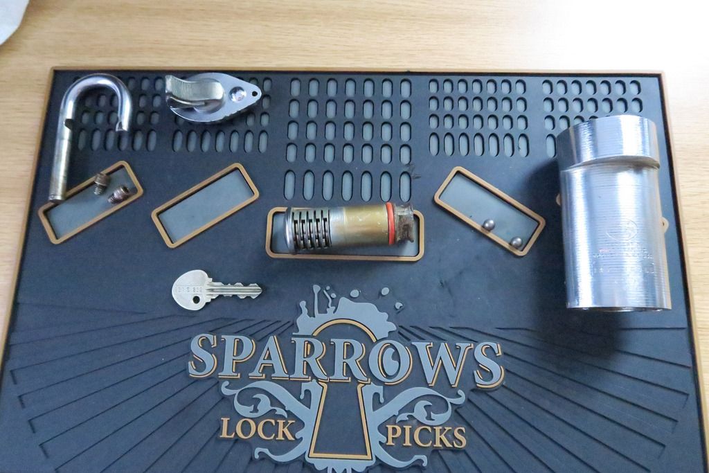
All parts stripped down so far:
Inside of the bottom plate:
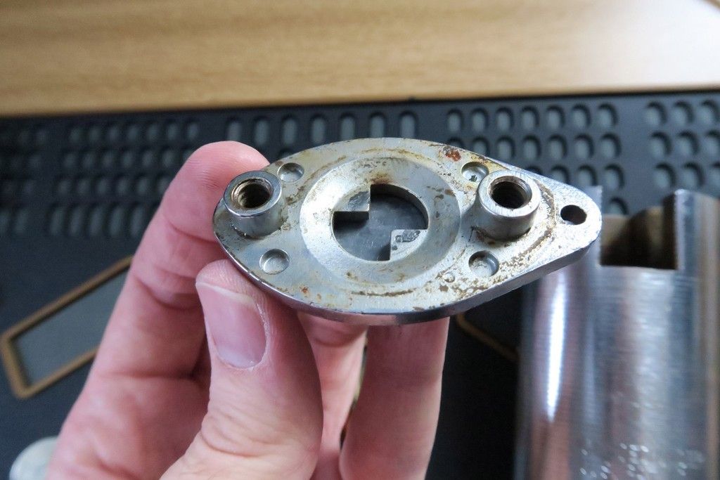
The screw retainers also act to stop the bottom plate from being rotated if just one screw was removed. Everything in this lock is also grimy as heck!
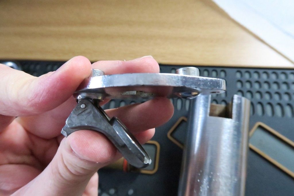
Bottom plate from the side, with snap-close pulled back. It’s pretty thick!
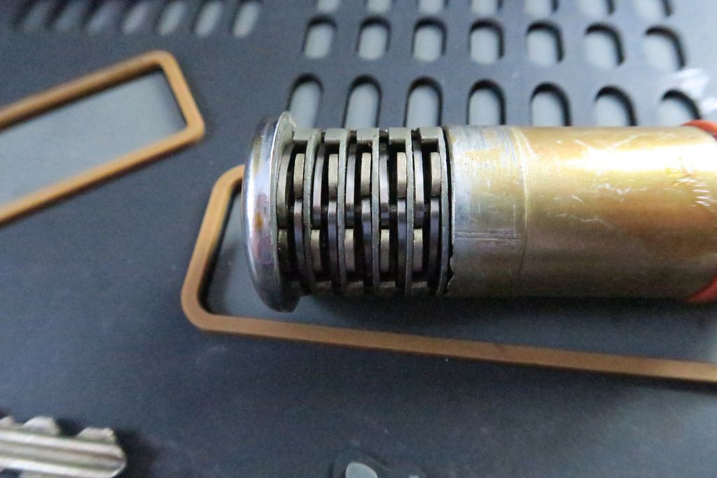
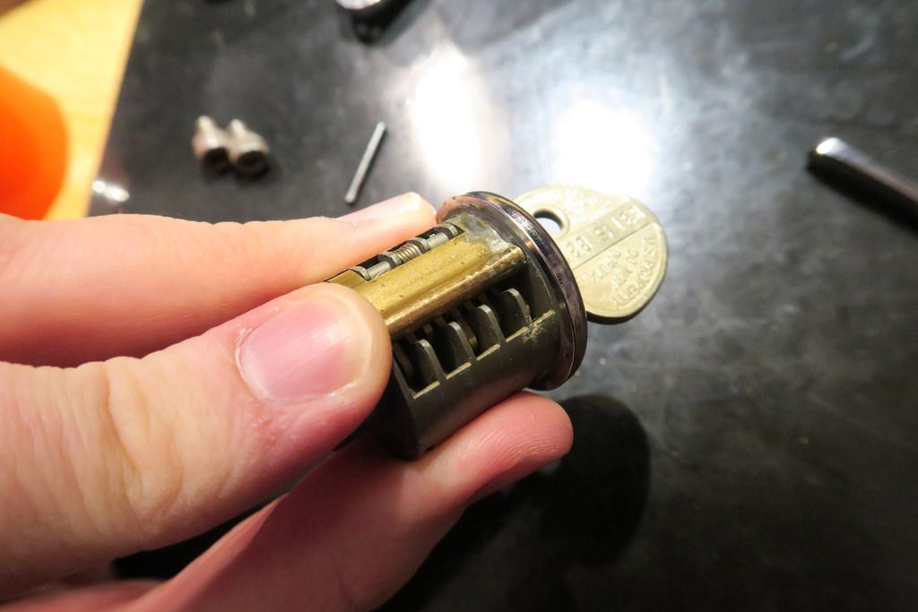
As is the front of the cylinder:
Note also the spring-loaded sidebar flopping around down there.
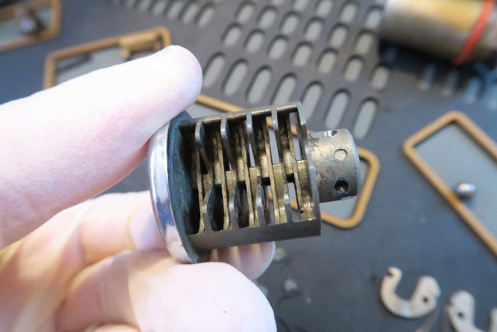
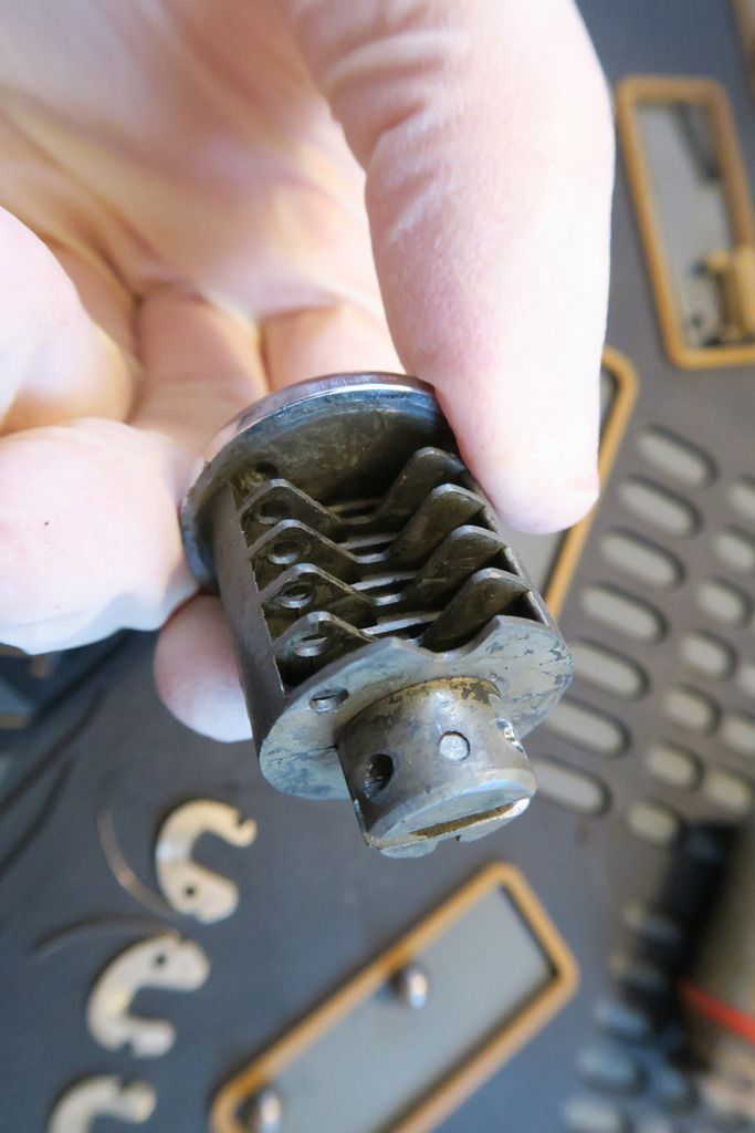
Actuator end:
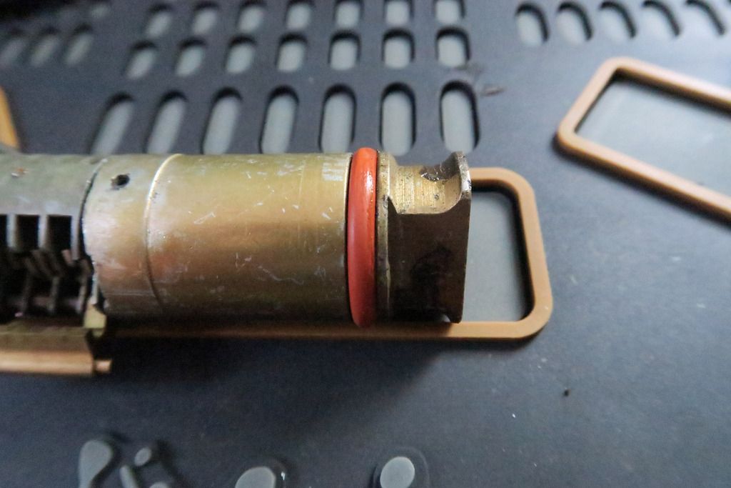
I assume that the long ends (slightly cut out) hold the ball bearings back when the lock is closed – as the key turns 90°, they will fall into the wide, flat edges when the lock is unlocked, allowing the shackle to be removed.
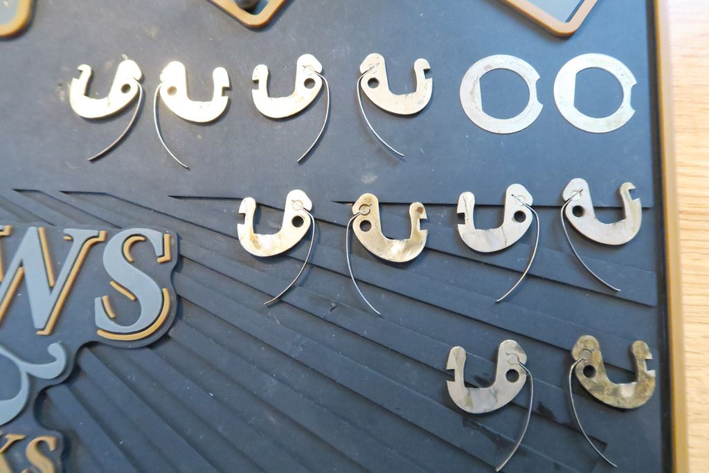
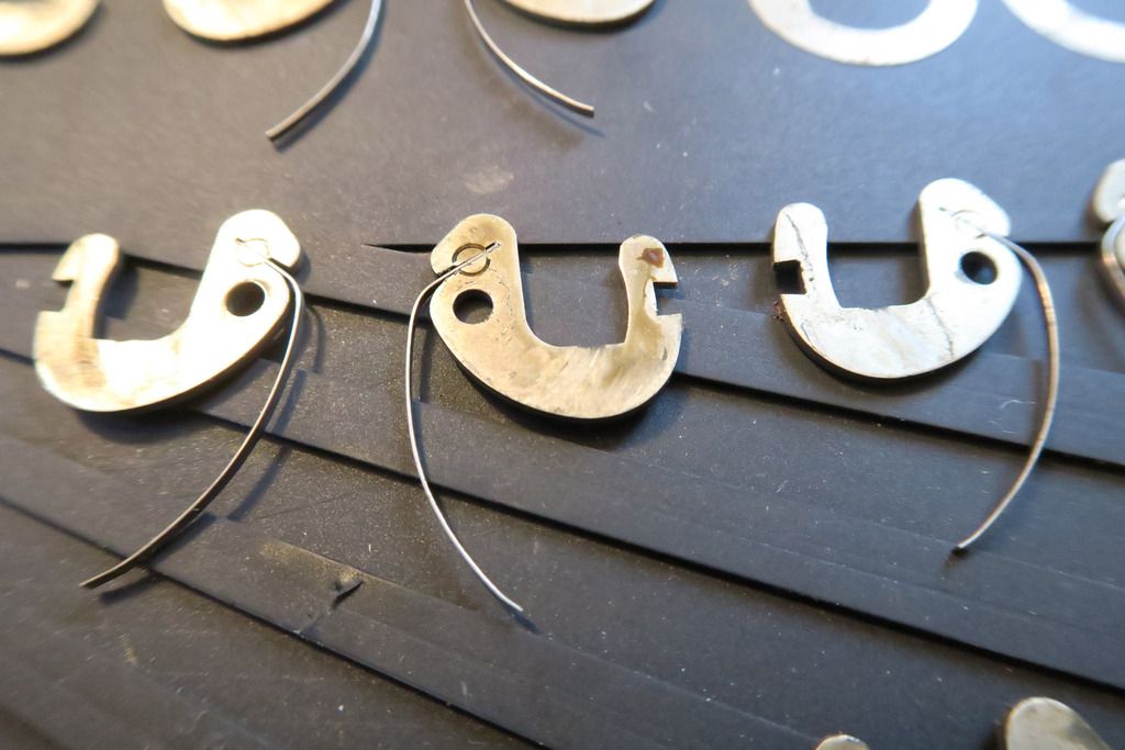
All the levers in place:
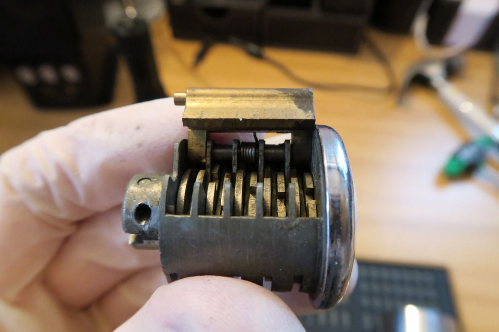
Down inside the body of the lock:
Note that it looks fairly well lubed in there – well, I actually stripped the lock down to this level once already, to check that it was possible, before re-assembling to do this photoshoot. It was a bit of a nightmare to keep the BBs in place so I loaded them up with a hearty supply of lube, and then lubed their respective holes, to keep them in place while I re-assembled. In actuality, when I first stripped this lock everything was devoid of lube and it’s all really grimy and rusty sadly.
One of the main issues of getting the BBs to stay in is that their respective BB holes are actually not flat against the bottom of the back of the lock body hole, but raised up by something like 5mm, making it impossible to simply roll them into place – you have to kinda lift them up and in with a screwdriver, and of course, as soon as you do one and move on to the other side, the last BB rolls out! Paired with the difficulty of finding the right place for the cylinder to fit so that the sidebar fits, the cylinder can rotate, and the key can be removed (only one one of two possible orientations) and it’s a real pain to assemble this!
Anyway, moving on

.
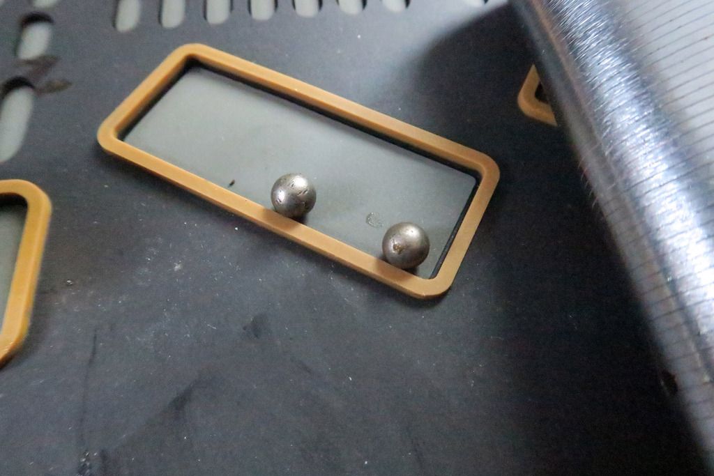
The ball bearings are smaller than I expected to be honest:
All the stripped parts so far:
This is as far as I got with my first foray into this lock. Everything from here on out is virgin territory!
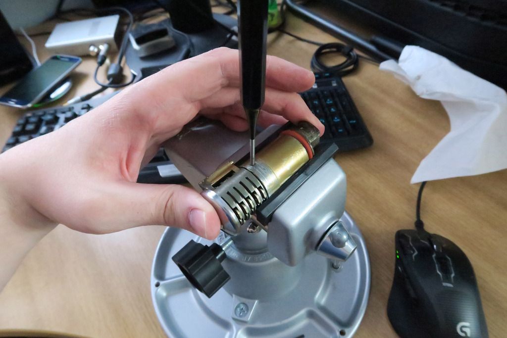
Since the lock is so grimy, I’ve decided (with the success of stripping the Abloy 656 cylinder behind me) to give total disassembly of this lock a shot! First we need to disconnect the Ingersoll cylinder from the brass cylinder that houses the actuator. To do that we have to punch out a roll pin kinda thing, of course, because this is an Ingersoll lock and nothing says Ingersoll like roll pins
There it is!
Two parts separated:
Inside of the back of the brass tube:
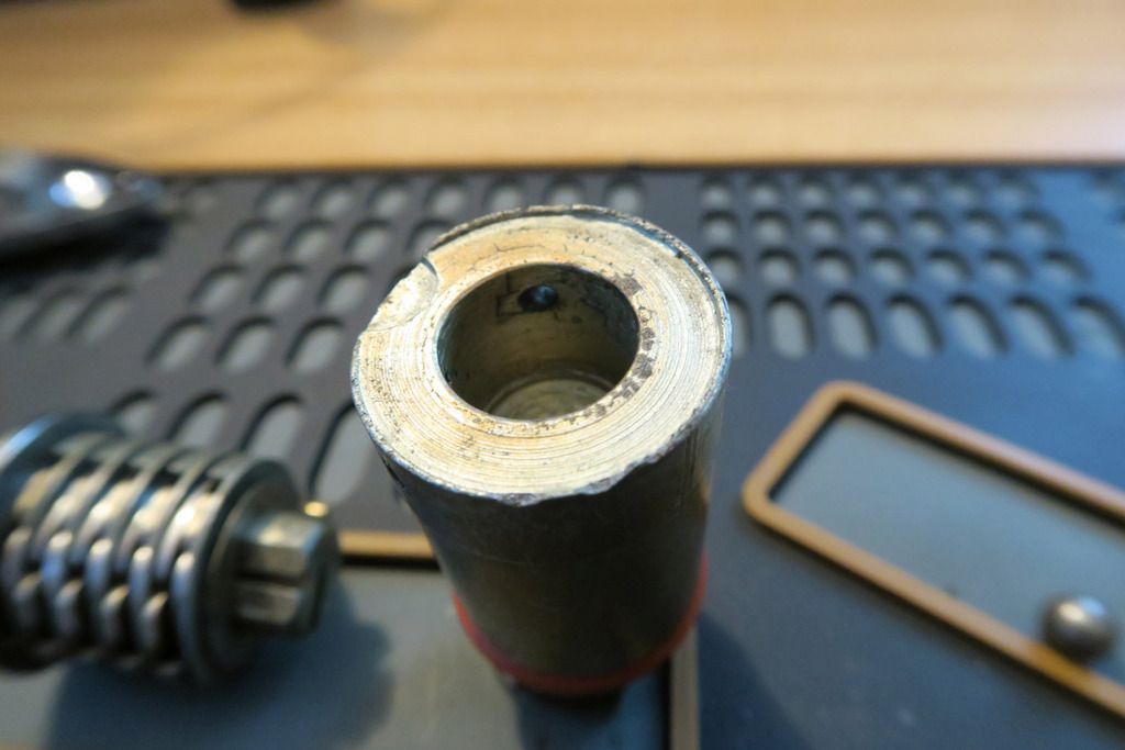
It has a cutout for the back of the Ingersoll cylinder – which I assume is usually the actuator (or connects directly to it) in other locks so due to the shortness of the Ingersoll cylinder and the length of this lock, the long brass tube was required to bridge the gap from where the ball bearings sit and the front of the lock. They decided to create a hollow tube to house the (pointless) rear actuator of the cylinder and hold it on with a roll pin rather than make use of the cylinder’s existing fittings.
What I’d love to see is a custom Ingersoll cylinder for this lock that’s the entire length of the lock and connects to the actuator on the end. It’d be, like, 30 levers and have an absurd key but it’d be awesome
.
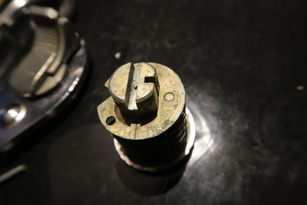
Here’s the back of the cylinder as mentioned:
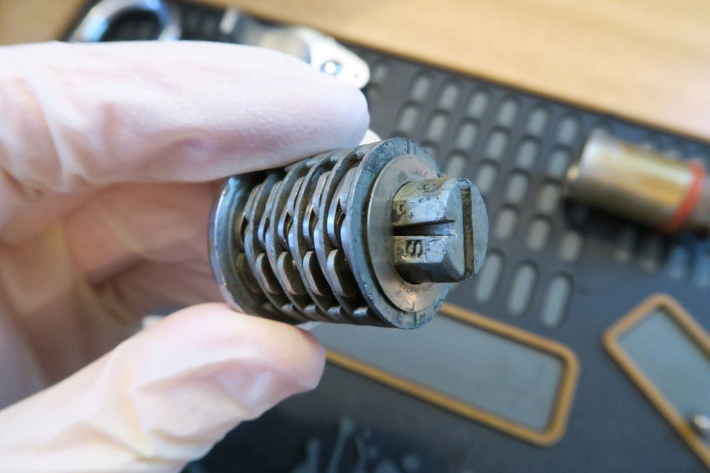
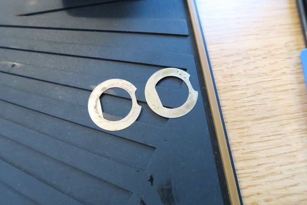
Note the thin disks at the back, I assume to act as washers? It’s also milled out with a slot to interact directly with an actuator.
I forgot to photo this directly, but on the back of the cylinder there are a couple more pins / roll pins pushed in that hold various things in place. One of these stabilises and acts as a hinge point for the levers, so we need to remove this to disassemble the cylinder. Unfortunately the pin is pushed in with no way to access the other end (since the front plate of the lock is smooth and welded directly to this cylinder), but luckily it’s easy to nudge out with a small tool and from there just grab it with pliers:
The disks are looser now and can be slid around to the other side of the cylinder:
Unfortunately despite trying, the disks can’t be removed with the sidebar contraption in the way, as that’s where they need to come out. I didn’t really want to remove this because it looks like the spring has been loaded onto the bar under tension, but that seems not to be the case after all thankfully.
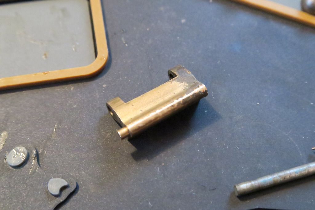
Sidebar, spring and it’s retaining pin:
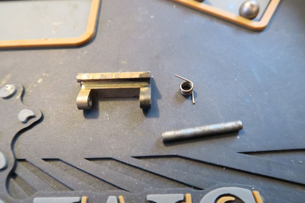
Other side of the sidebar:
All the little bits:
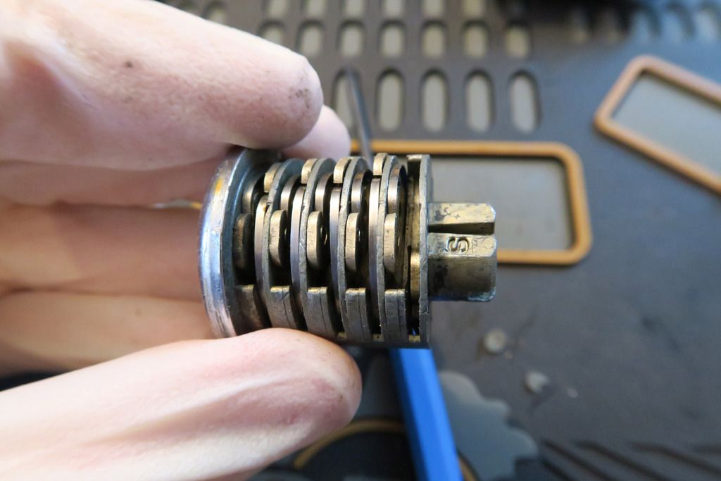
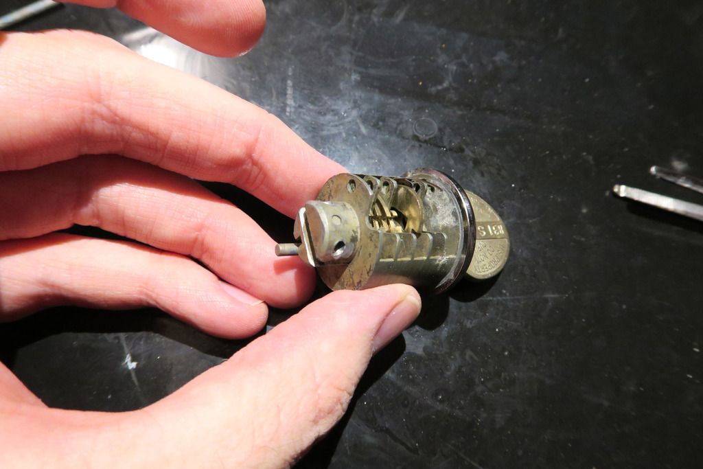
“Open” side of the cylinder with levers in:
Removed the two fine disks from the back of the cylinder:
To remove a lever, push the rounded nub down as far as it can go (note the gap on the far right):
And then flip over the cylinder to see the lever sticking out:
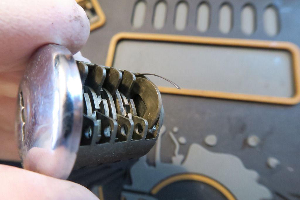
You can then remove it:
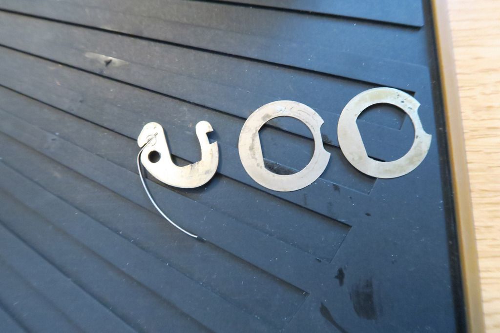
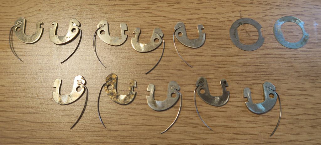
Don’t lose the order of the disks!
Note that every other disk comes out the other way round – i.e. you slide it in the opposite direction and it’ll come out of the “back” of the cylinder the other way round. I assume this is one lever for each side of the key. Carefully slide them all out and line them up:
Closeup of a lever so you can see how the spring is fitted:
I’ve still not yet worked out how these actually work. The square “true gates” (though there are no false gates) on the right hand side of this lever (alternately left and right) is where the sidebar slots into, on the back of the cylinder, when the lever is rotated correctly. When all the gates line up, the sidebar can be pushed into the gap (under spring tension) and the rotational pressure of the key will turn this entire cylinder within the lock body, in turn rotating the actuator. The spring which hangs down from the lever pushes the lever back up into its natural position when the key is not present, “scrambling” the lever combination when the key is removed (without that, the levers would stay in place, allowing the cylinder to be rotated without the proper key).
The round hole is where the metal rod goes through, and acts as a hinge point allowing the levers to rotate around that point. I assume the key fits between the large cutout in the lever, and the cut in the key rotated the lever to a specific position. The “gates” in the levers are cut at different positions, so when the correct key is entered the lever will be rotated to the correct position for the gates to line up. However I’m not 100% sure that this is how it works and is only speculation on my part. Small wear scratches on the disks (you can just about see them on the last photo – directly at the bottom of the large cutout in a semi-circular fashion) indicate (I assume) where the key interacts with the lever.
Cylinder emptied (levers removed) – this is the “closed” / front side, note that the silver disks go all the way around:
The back edge of the levers (where the spring connects) bump up against the bottom silver metal pieces here.
“Back” side of the cylinder – the silver disks have large cutouts in them:
This is the side where the levers are removed.
Back edge from an angle (you can see where the pin goes through, which holds the sidebar unit in place, allowing it to pivot down into the hole between the big silver disks and interact with the gates on the levers):
Front edge of the cylinder from an angle. You can see where the pin goes through, holding the levers in place and causing them to pivot here:
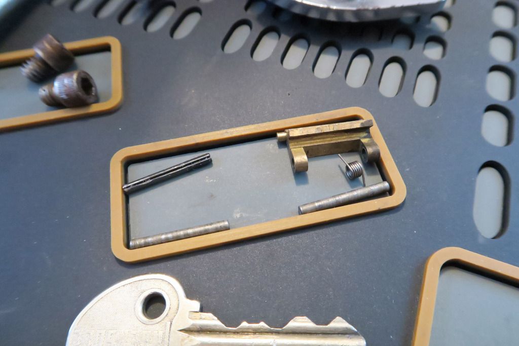
All the parts, totally stripped down (as much as possible):
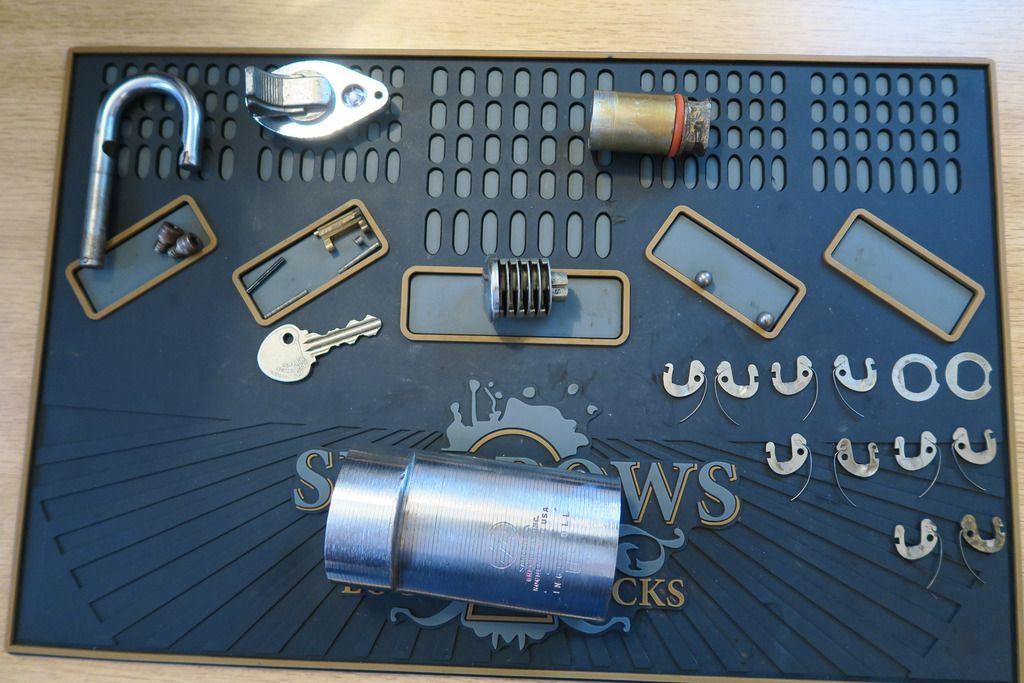
Here we have the shackle, two bottom plate retaining screws, bottom plate, actuator cylinder, small section includes rod to hold cylinder to actuator (top left), rod to hold levers in place on which they pivot (bottom left), sidebar, sidebar spring and rod to hold that in place. Empty cylinder, two ball bearings for the locking mechanism, key, body, levers and two spacer / washer disks.
Next up is the good ol’ soak in GUNK. I forgot to get any photos of this stage, but basically I put all the small pieces (everything but the body and levers/two spacer disks) in my usual small pot of GUNK, and filled up a bigger container to house the lock body. I didn’t want to get the levers mixed up (not as easy to fix as pins since I don’t really understand how the mechanism works yet) so I kept those out and cleaned each one individually with WD-40 as best I could.
Levers cleaned (not great I know – most of that black stuff won’t come off, wonder if it’s rust or something?):
As of this time of writing the other lock stuff is still chillin’ in GUNK, so I’ll fill in the rest of this when it’s all cleaned up!
....
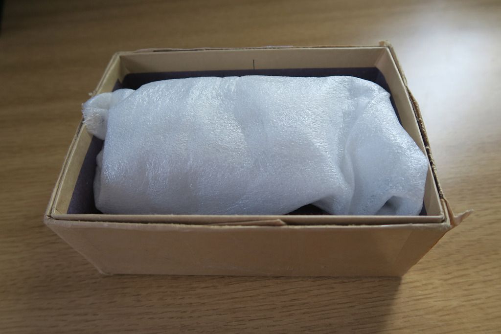
Alrighty! Picking up where we left off. Here’s a box of freshly GUNK’d bits:
I started off cleaning the lock body, which unfortunately is very rusted inside. The screw holes are nearly impossible to get into with a cloth, even loaded onto a hex screwdriver (my fave trick for dealing with these). Rusty brown crap just keeps coming off and off – I’m not sure if it’s even possible to completely clean the inside of this body, but here’s how the cloth looked by the end of it:

That’s just one side.
Eventually I decided it was time to move onto the other parts. Discolouration tended to stay and some stuff was just too rusty to get clean but I’m overall happy with how it turned out
.
Now it’s time to re-assemble. Levers are loaded back into the plug in the same way that they came out:
I realised pretty quickly that you want to load the pivoting rod in as you go, since they’re hard to align properly and easier to do one at a time:
All the levers loaded back in:

Back of the cylinder (I remembered that I forgot to photo this before):
Still looks a little scrappy but then it is an old lock! You can see the “filled” rod hole to pivot the levers, and the empty hole where the sidebar goes.
With the key in, all the gates line up:
Sidebar loaded back on:
Thankfully the spring wasn’t too hard to get back in place!
Testing the sidebar... And it works!
Cylinder re-attached to brass plug with roll pin:
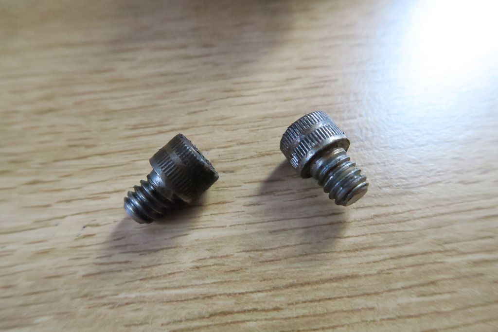
The nuts look much better now:
Oh, and it turns out that they actually *are* hex nuts, not torx. Turns out that even with my fairly big set of long hex screwdrivers, I don’t have one the right size to fit this particular nut. I do have a bigger range of “regular” L-shape hex keys but they’re too short to fit into the shackle hole. Thankfully I had a Torx driver which was the right size and happened to operate the screw – otherwise this would be a MUCH shorter post, hah!
With the cylinder re-fitted and screws back in, it’s time to punch out the pin in the shackle again to lock the shackle inside the lock body. This turned out to be a bit harder than anticipated as the pin just –did not- want to move. Luckily we got there in the end! I managed to get a couple of photos, too. Here’s the sticking-out end – if you move the shackle around you can get it to stick out into the body hole:
You can just about see the recessed side here:
Still pretty rusty inside the lock:
I’ve ordered some rust remover from Amazon (I think it’s called Jenolite) so we’ll see if I get any luck with that! In terms of lube, I used Tri-flow on the cylinder (zipping the key in and out to work it through) and Lithium grease paste on the bigger parts – ball bearings, actuator, shackle depressions etc.
Re-assembled:
It does feel much nicer to operate now, especially the key which inserts much more smoothly and the cylinder turns more smoothly too. An overall success, I think!
Looking forward to adding it to the “wall of fame”
.