Okay, so I have something very, very cool to show you today. I didn't really know much about these when I bought this, other than it sounded and looked awesome, but I've since done a bit more research into both the lock body and cylinder so the below may have some inaccuracies, apologies if that's the case.
I do actually have the original box for this as well, but I’ve already packed it away. Anyway, without further ado...
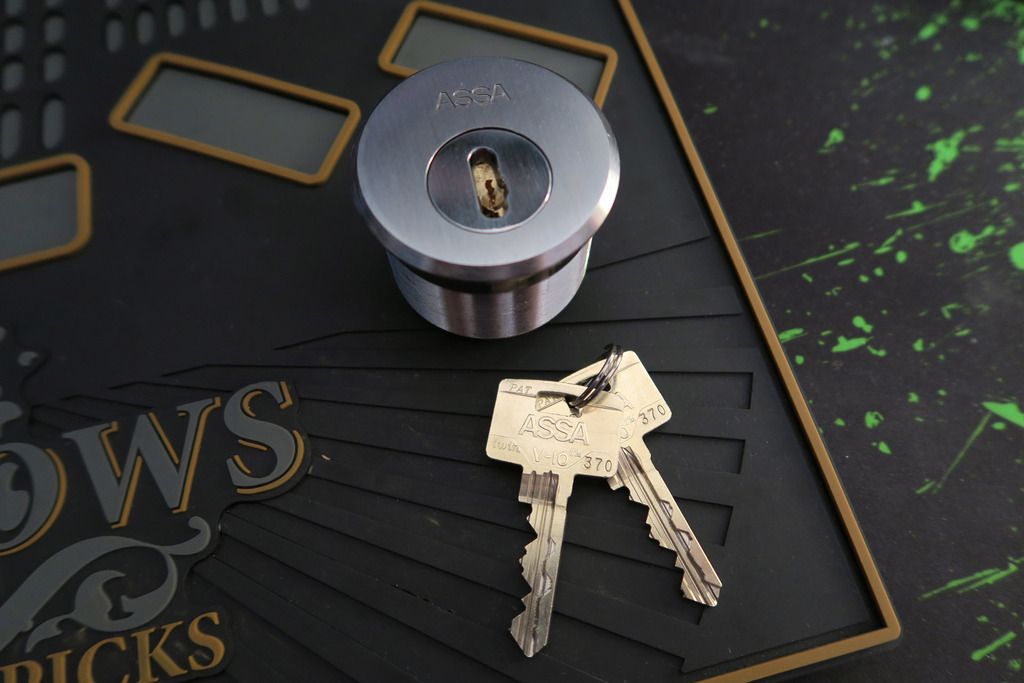
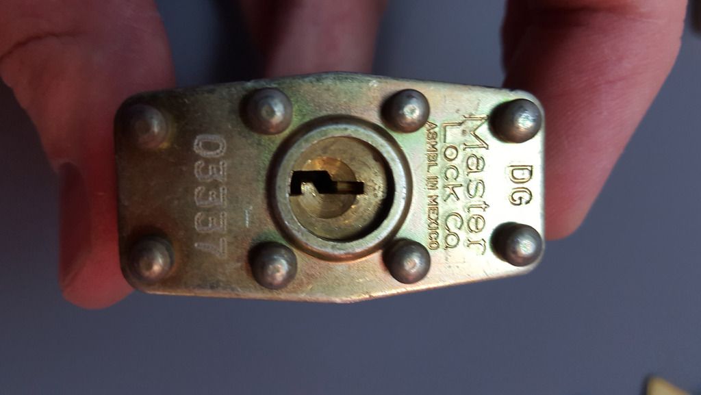
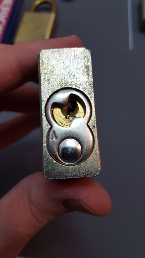
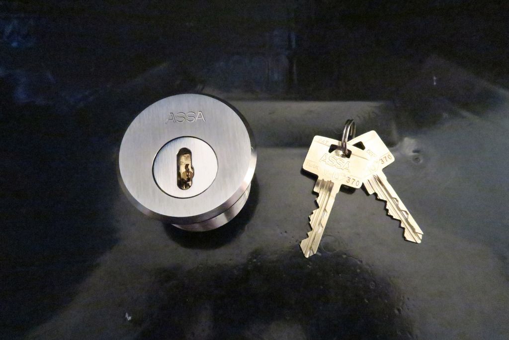
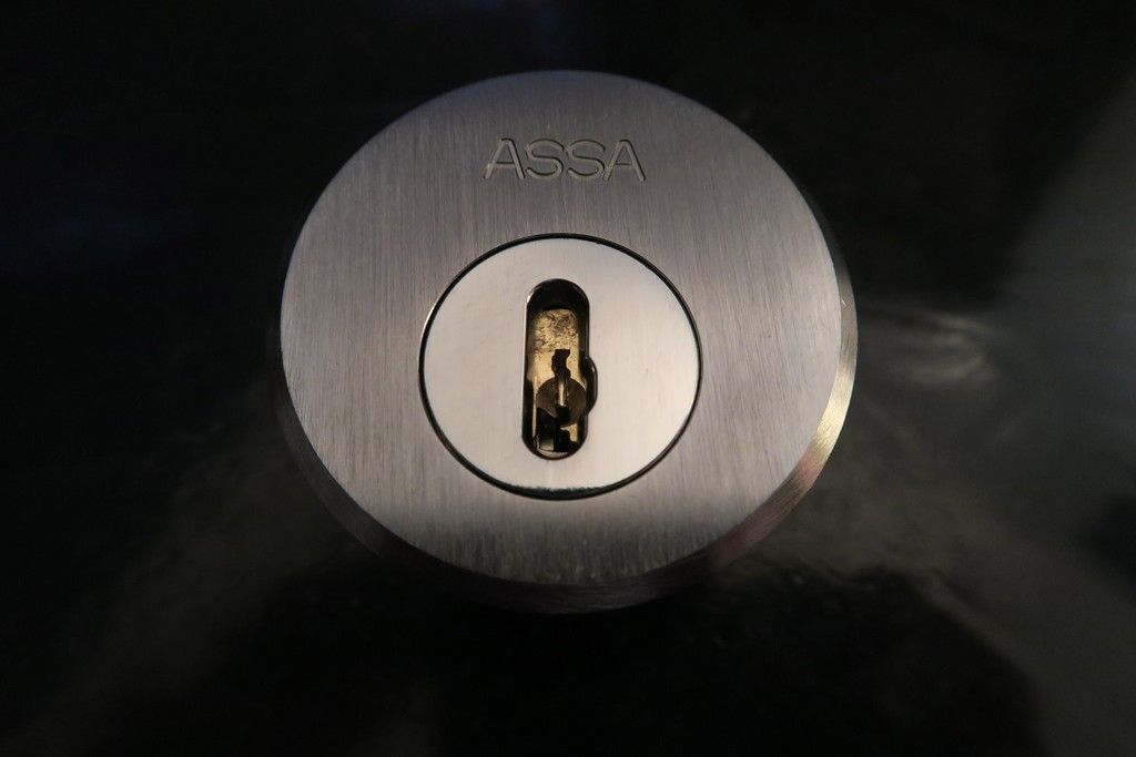
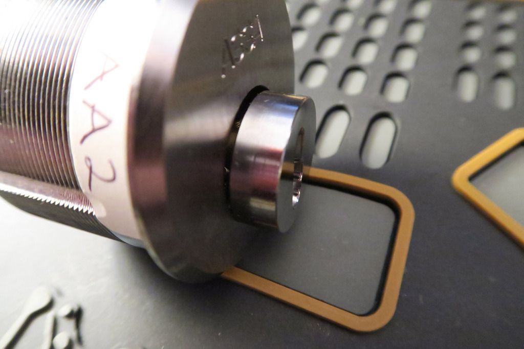
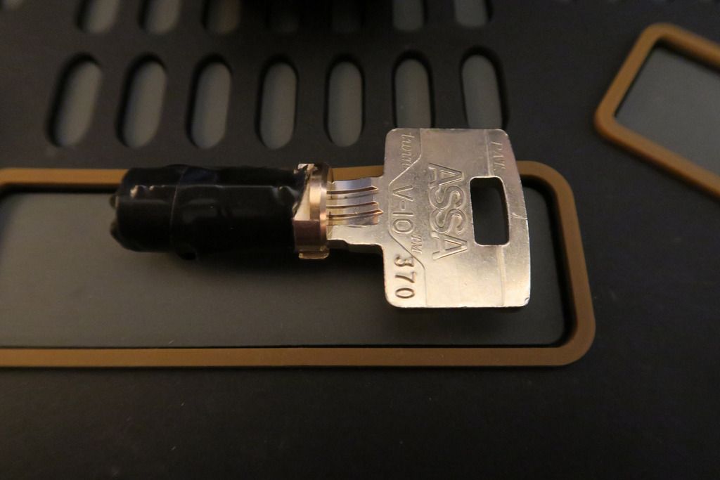
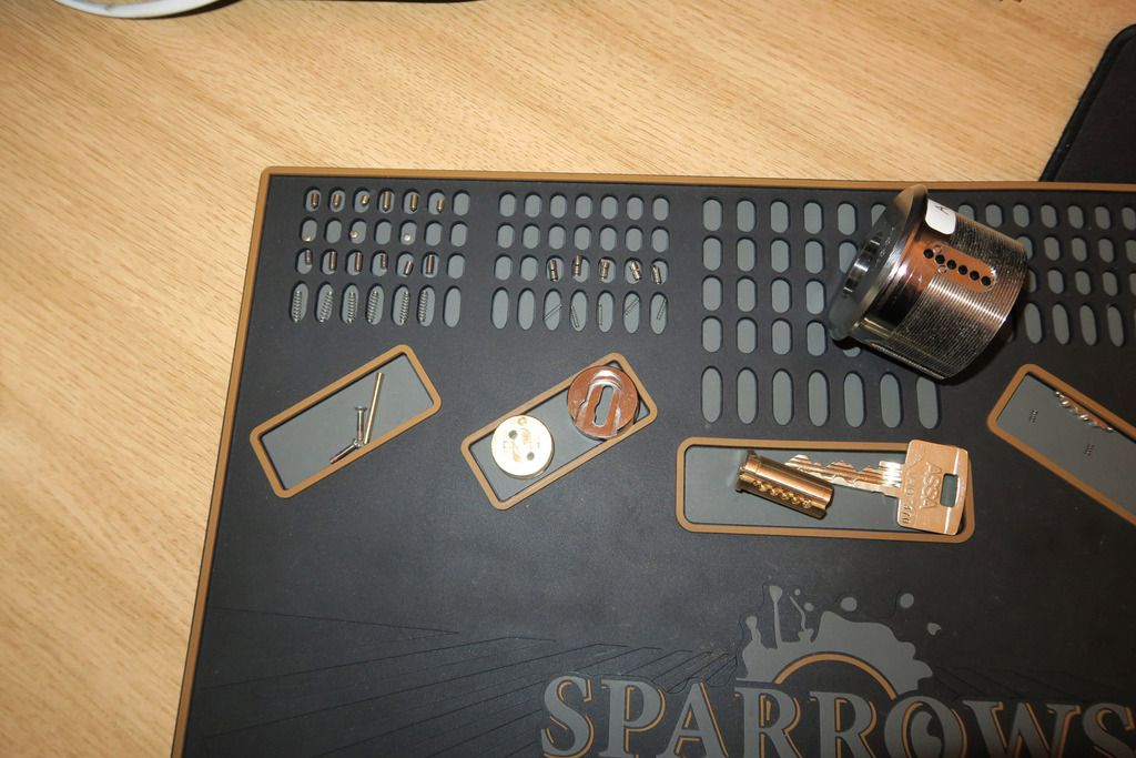
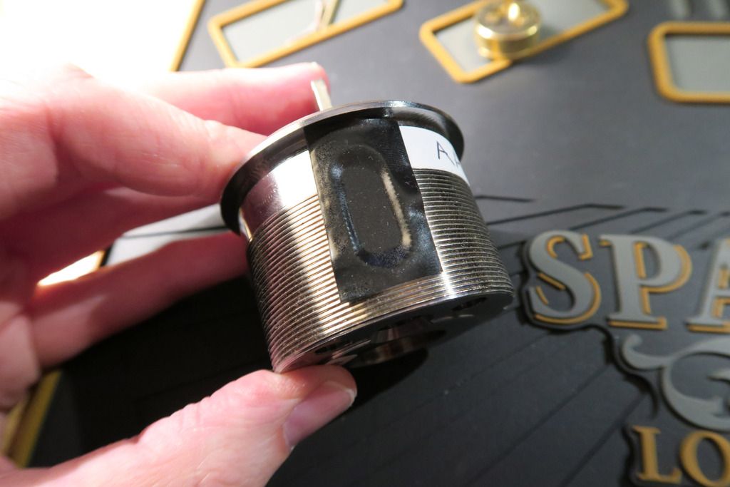
It’s an Mogul, fitted with an Assa V-10 core. The Mogul cylinders are detention locks designed for prison doors and the like – as such it has a hugely heavy and chunky casing which is all but vandal-proof. This unit is comprised of the large outer shelf, an armoured front plate (that’s the shinier silver bit you see in the middle of the large outer disk) and the cylinder itself, as well as... Well, we’ll get to the internals soon enough

.
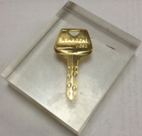
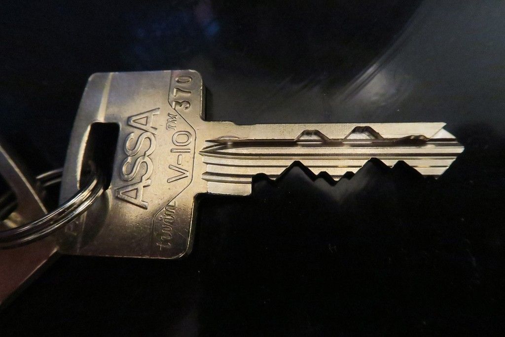
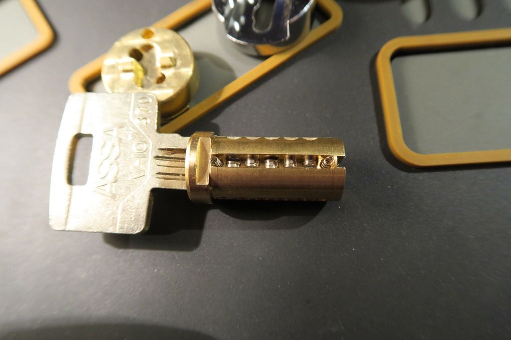
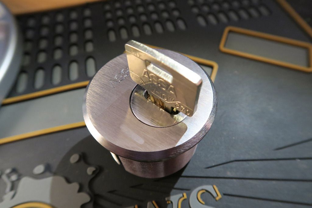
You’ll notice the keys are interesting – they have two lines of bitting. These are Assa Twin keys, and the lock has both “normal” pins and also a kind of sidebar / side pin system:
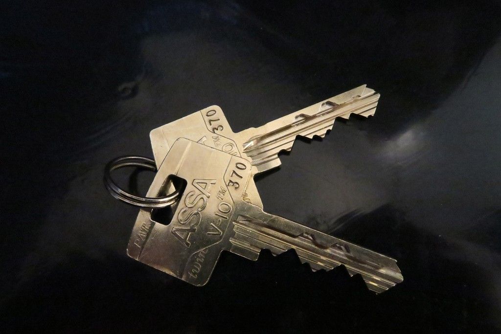
I love these keys, so cool looking:
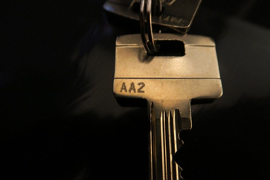
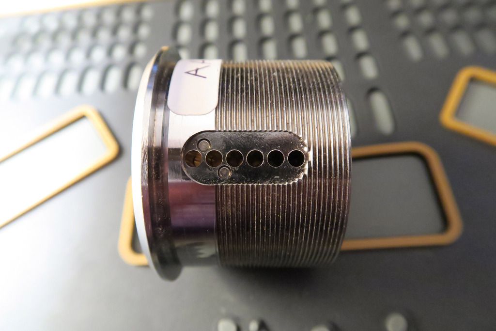
The keys are stamped “AA2” on the back. The cylinder itself has a sticky label which says “AA3”. I had no idea what this meant until I just googled it literally a few minutes ago and found an awesome PDF from ASSA called “Master Key System Design Guide” which shows that it’s a way of designating master key levels.
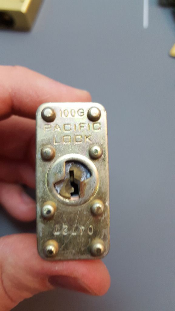
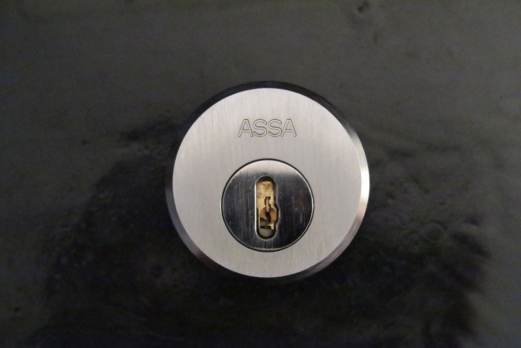
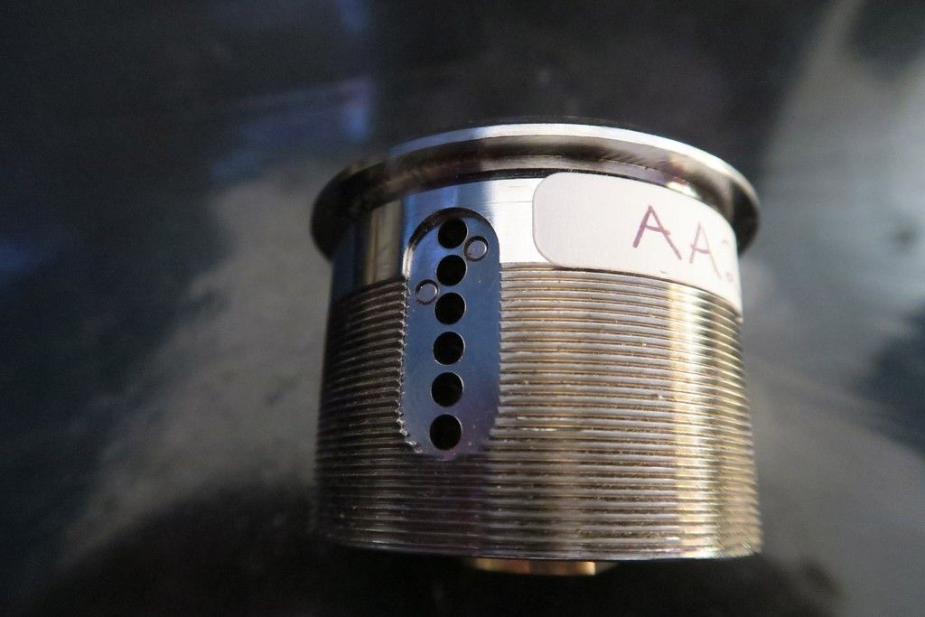
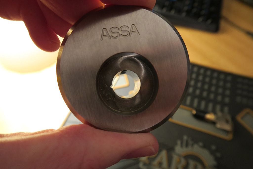
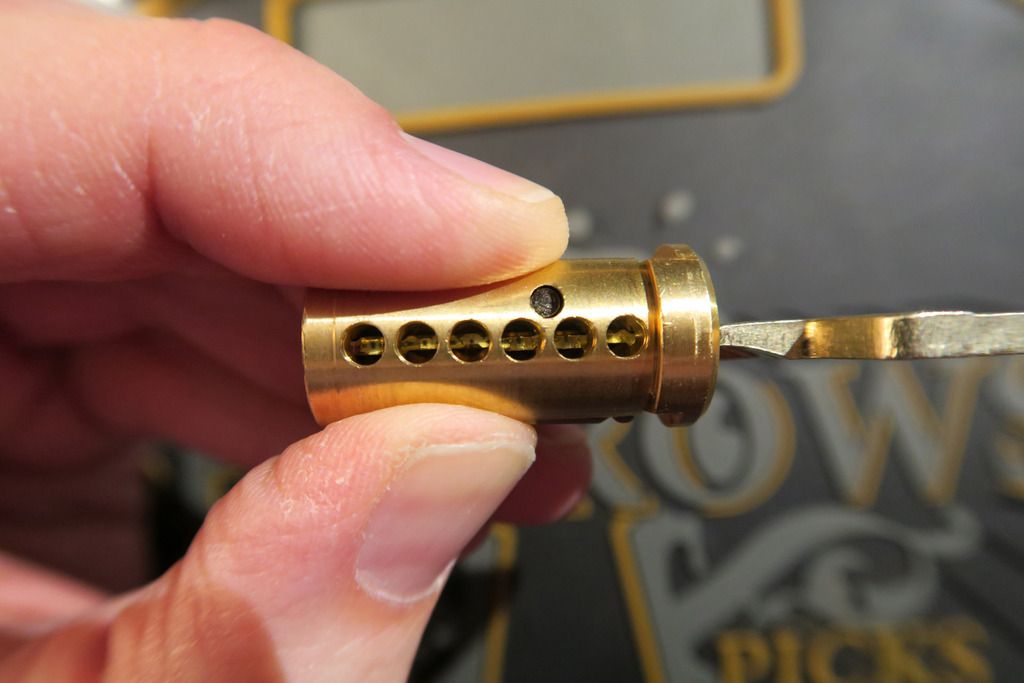
The front of the cylinder looks imposing and awesome:
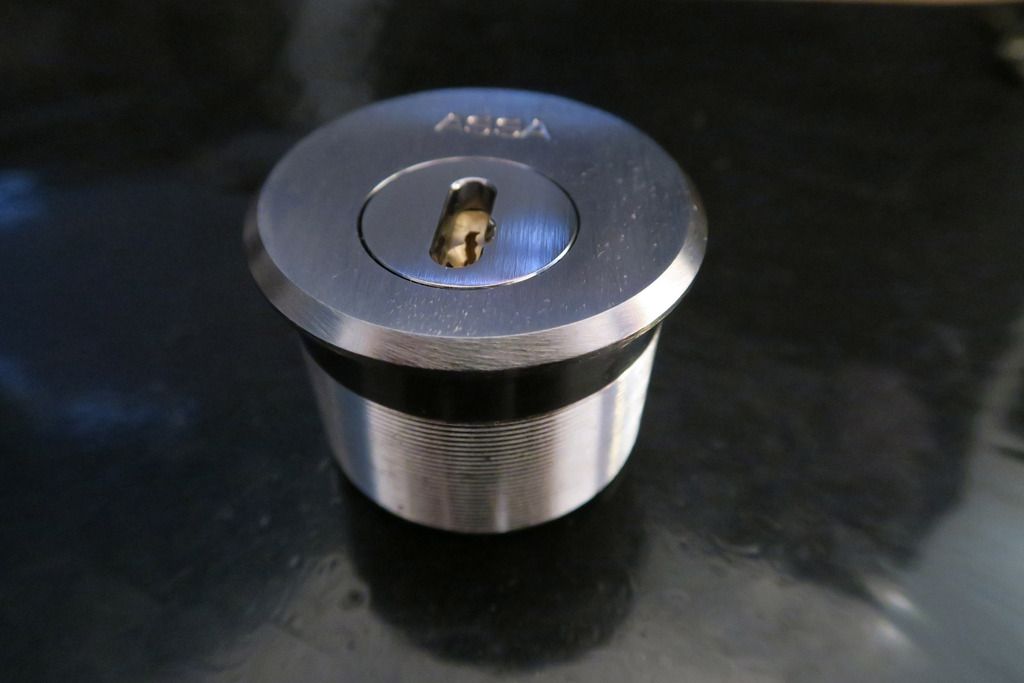
Life goals: Find a way to fit this to my front door, hahaha:
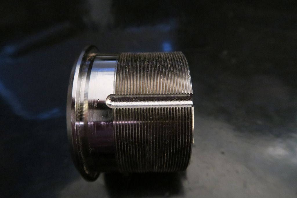
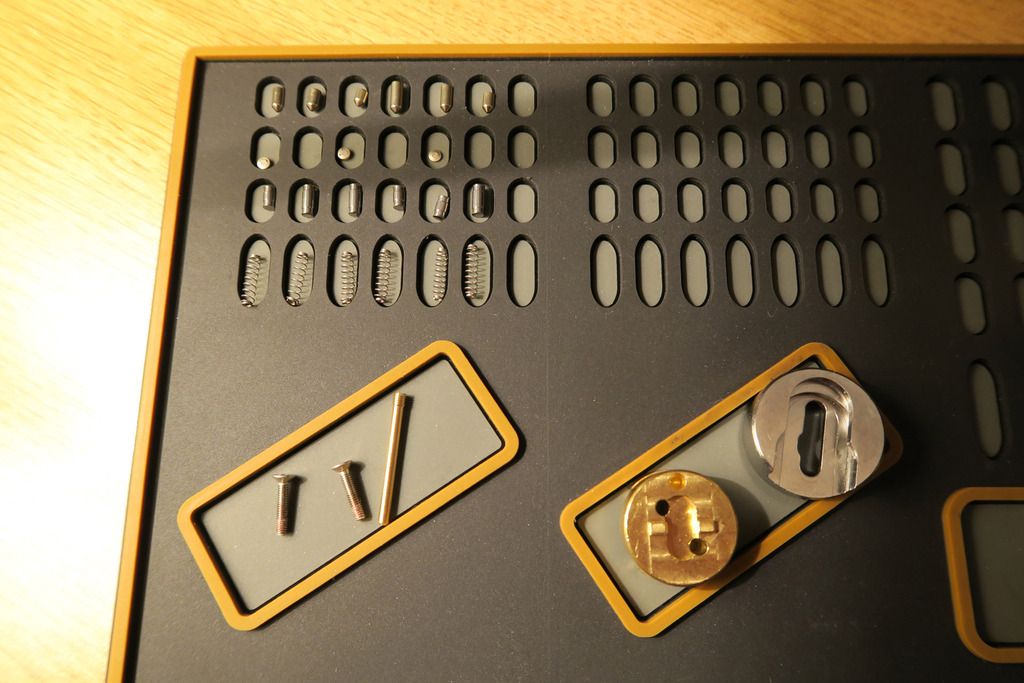
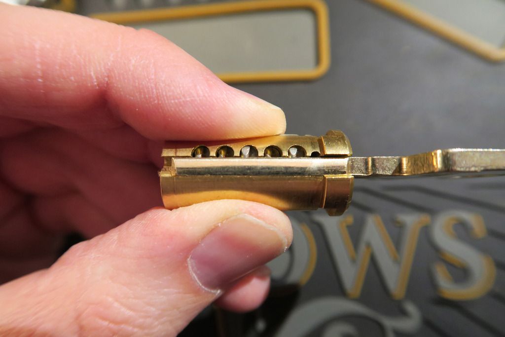
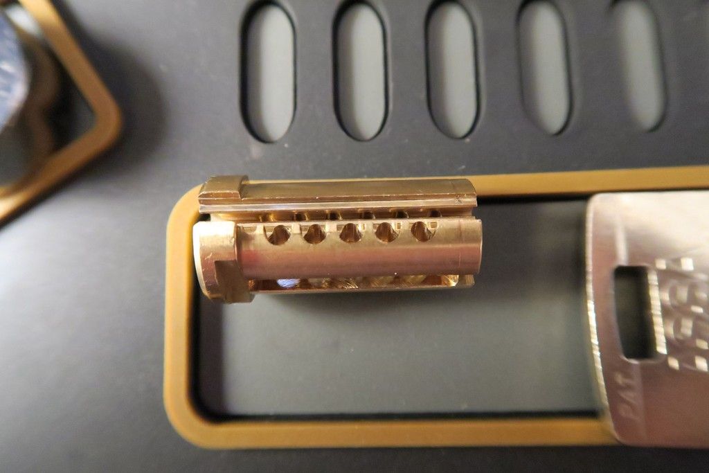
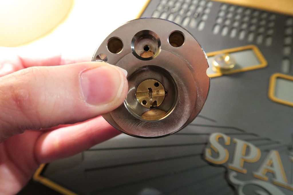
Pin chambers in the outer body? You may be asking. Why yes, I’ll get to that:
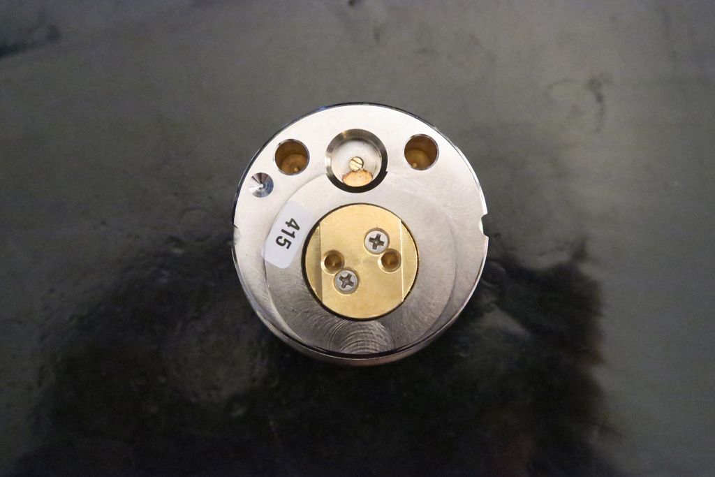
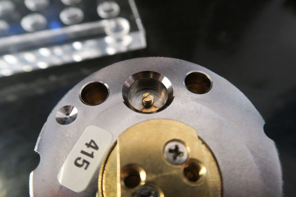
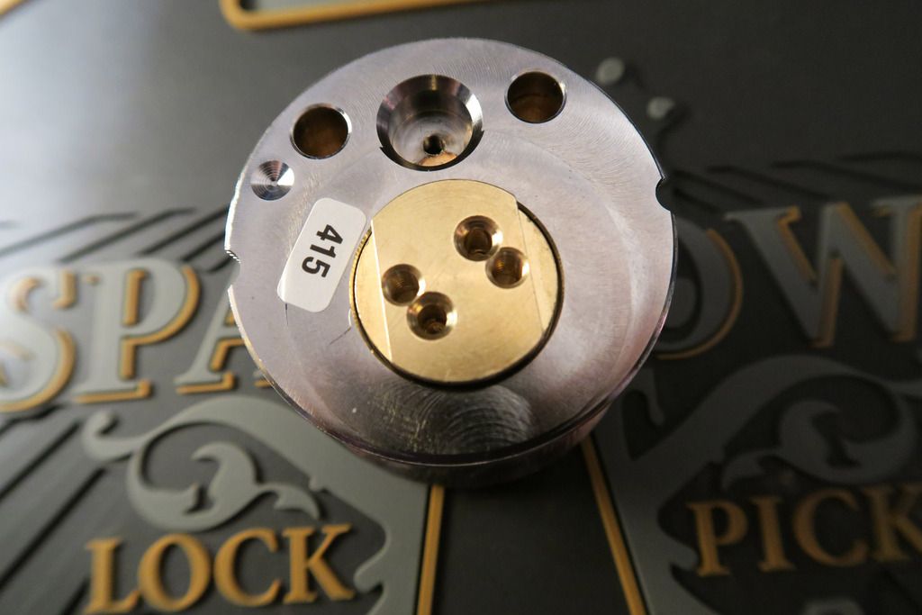
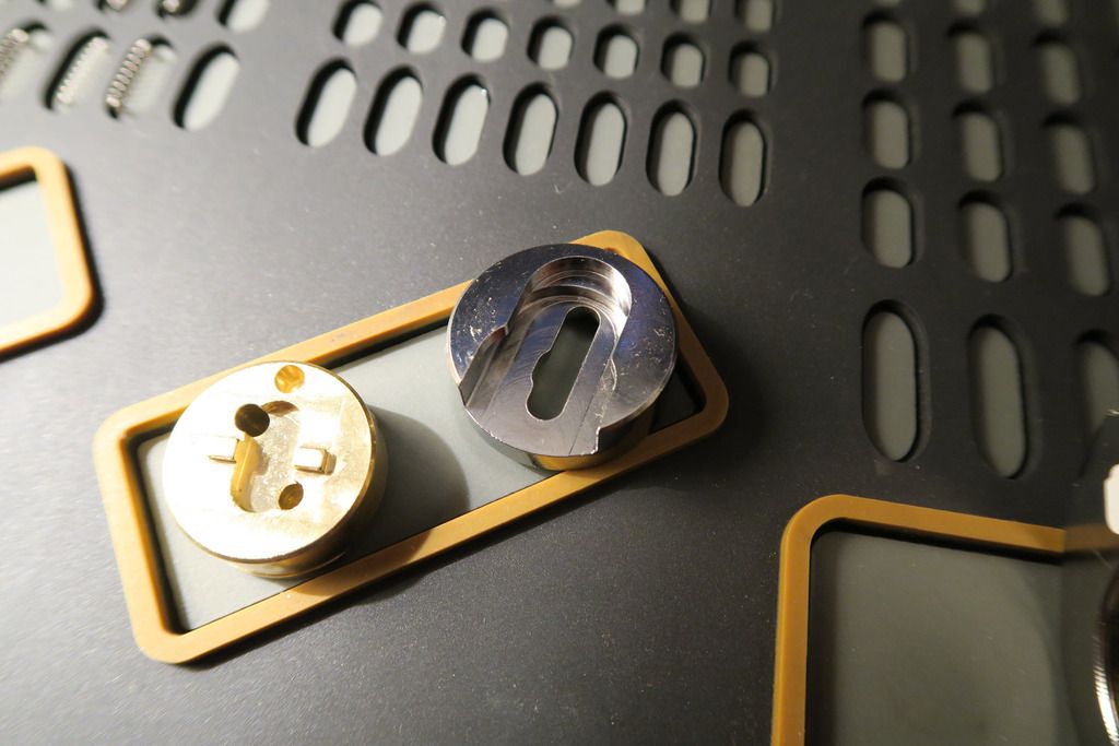
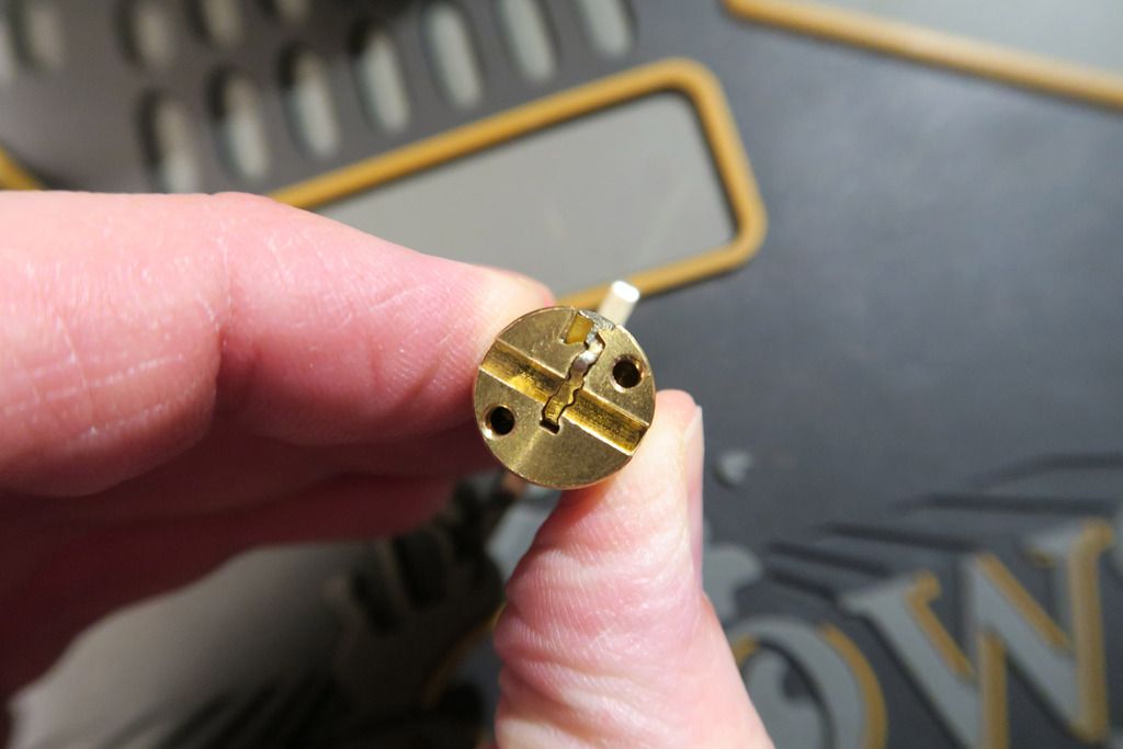
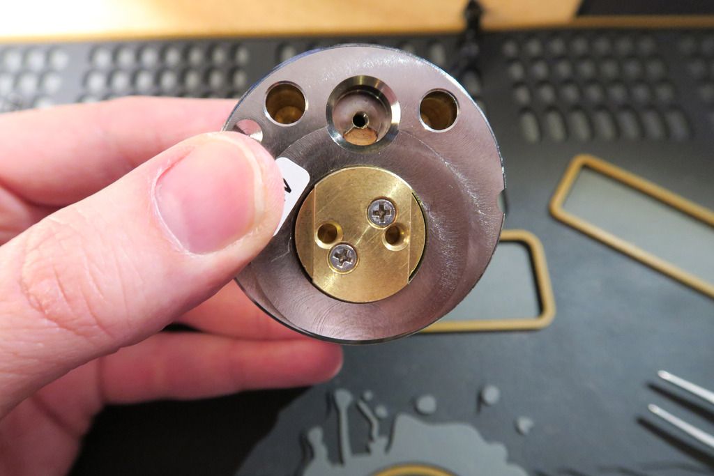
The back of the lock. So – in the middle we have the actuator, which screws onto the back of the plug. Above that we have three cutouts – two on the left and right which I assume are to do with fitting this into the lock body. The one in the middle is interesting – you see that little brass screw in the middle? We’ll get to that soon.
Now would be a good time to point out that the following disassembly is not the first time I disassembled this lock. This time, I did it carefully and under controlled situations (I still had some issues, but not many). The first time was just after I received the lock. It was new and exciting, and I figured “Oh, it won’t hurt to quickly pop the plug out and take a look at it before I pop it back together and start the teardown! Won’t take 2 minutes”. So, that’s all well and good until I started sliding the plug out and pins, springs and side pins started popping out and flying EVERYWHERE. On the plus side I learnt a lot about how this lock works as I spent the next SIX HOURS putting it back together. You live and learn!!
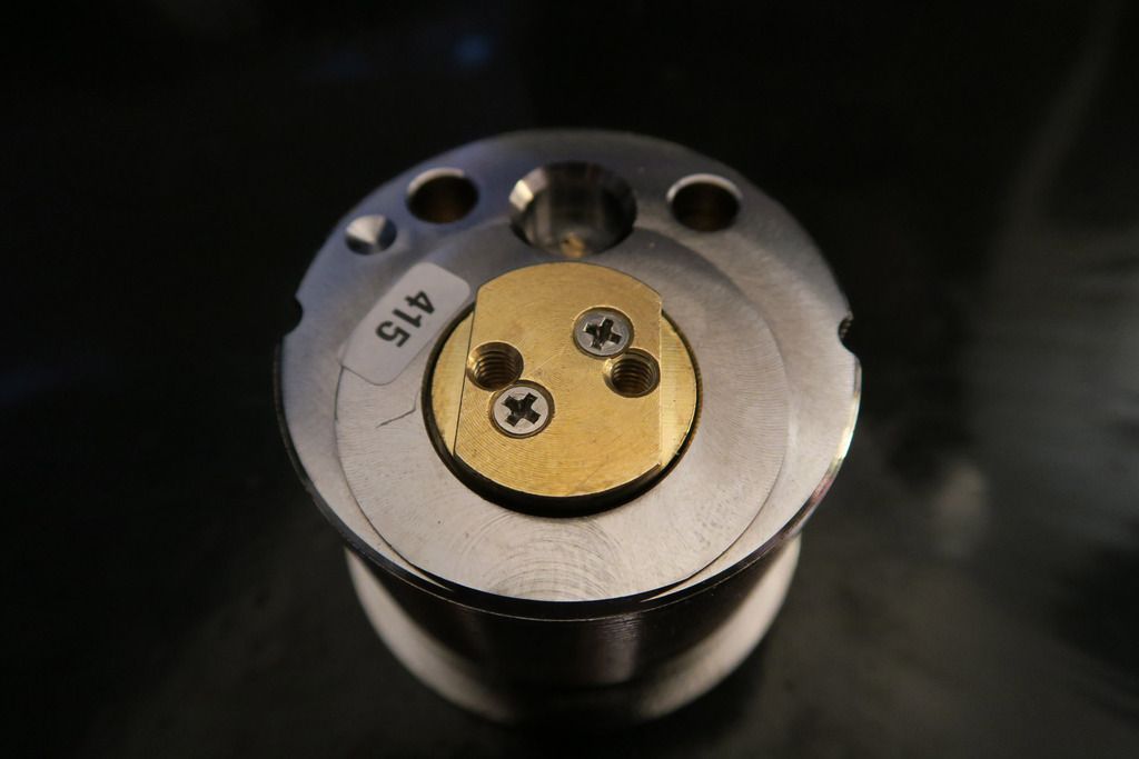
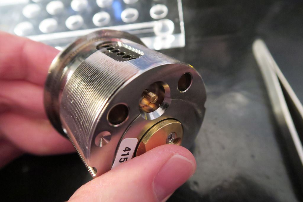
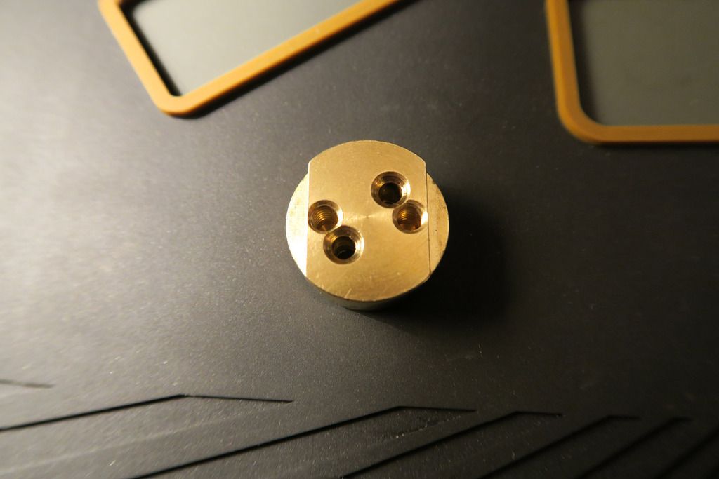
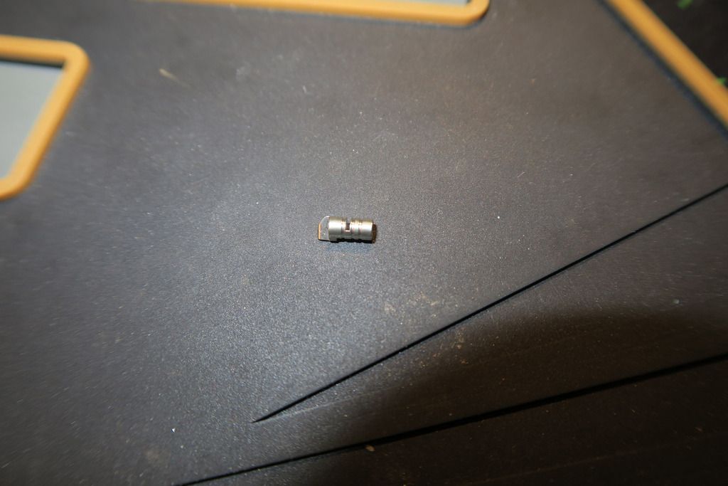
So, moving on. Close-up of the actuator:
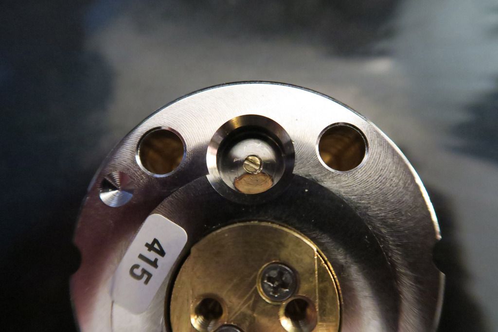
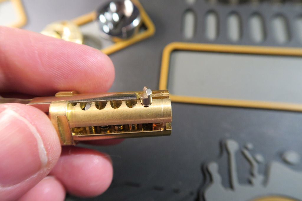
And that brass screw. When I first saw this lock I couldn’t figure out what the pin chambers in the top of the lock body were for – I assumed that maybe the lock had a second set of pins, separate to the plug that somehow locked the plug in place? Well, it turns out that this little screw isn’t just a screw...
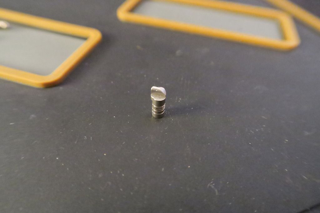
When you unscrew it...
You’ll find that it’s attached to a long brass rod. Below that, the springs, driver pins, and finally the plug and key pins / master wafers can be found. This is simply an efficient way to pin up the chambers without having to use a plug follower – simply pin up the plug (I guess you could technically do that through the top holes too, but I found that the master wafers kept getting caught), slide it in and then pin the drivers and springs from above. There’s a trick to getting the bar back in, as the springs necessarily sit higher than the bar (to provide spring tension) – the way I did it is to push the bar up against the spring like when you use a plug to trap the driver pin in place in a regular lock, then use a thin, flat screwdriver to push the spring down. Pull up on the screwdriver whilst pushing the rod forward and it’ll slide into place!
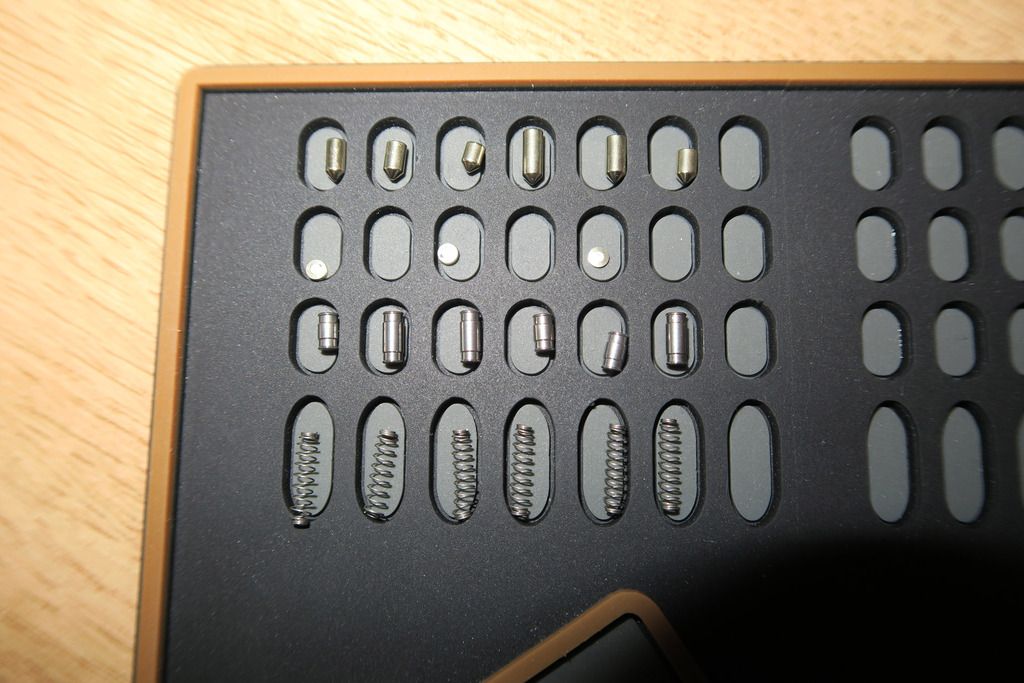
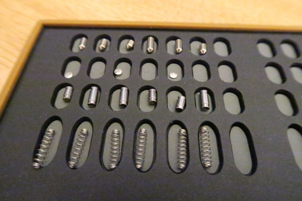
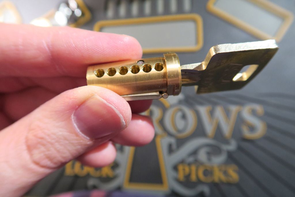
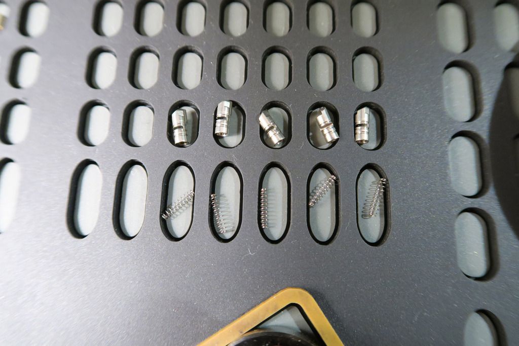
Here’s one of the pin chambers. There are a LOT of parts in this lock – not least because of the master wafers in mine:
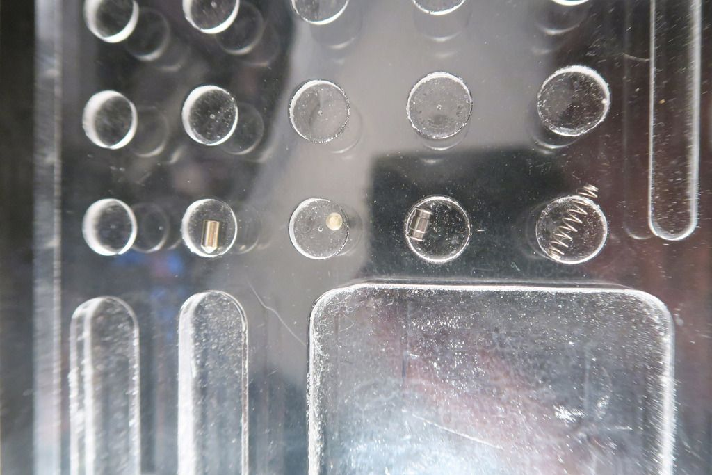
Pins removed:
So we have six pins, three master wafers, six drivers and six springs – this isn’t counting the sidebar stuff. All the drivers are like.. Weird spools. Reverse spools? They have sharp spool edges, then a dip, and then a wider middle section. Interesting stuff. Key pins are standard:
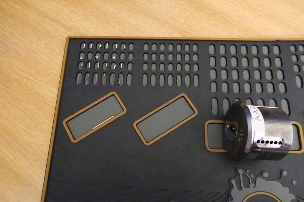
Empty chambers:
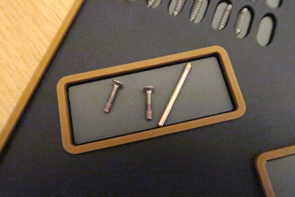
There’s that long rod that I was talking about, and also the two screws which attach the actuator plate to the back of the cylinder:
Back of the cylinder and actuator with the screws removed:
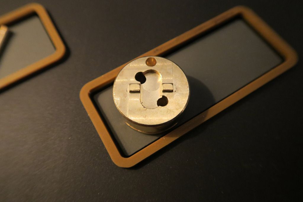
Actuator plate:
The inside fits into the back of the cylinder. It’s really heavy-duty and thick, just like the rest of the lock...
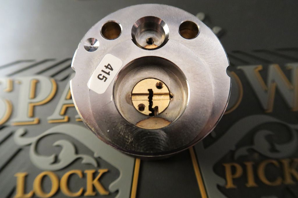
Back of the lock unit with the actuator removed exposing the rear of the plug:
Plug coming out of the front (well, technically this is an armoured plate which slides onto the front of the plug to protect it. Also: the bane of my time with this lock, as I kept carefully re-assembling all the parts in the plug only to forget this front plate – which you can’t add with a key in the plug – and had to start over. D’oh!):
Rear actuator plate and front cylinder protector:
Front of the cylinder with the plug and front plate removed:
All the “loose bits” so far – key pins, master wafers, driver pins, springs, actuator screws, pin loading slot rod, actuator and front plate:
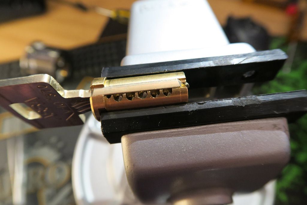
Here’s the key in the plug, which is wrapped in black tape. For good reason...
... Because not only does the plug have the regular pin chambers (which are even more finicky than usual when fitted with paper-thin master wafers), it also has five side-pins (and springs) AND a sidebar, which are ALL loose and will come out of the plug (the key holds the side pins in, but that’s it. Also they’re under spring tension, so remove the key and you GUARANTEE that pins will go flying across the room...):
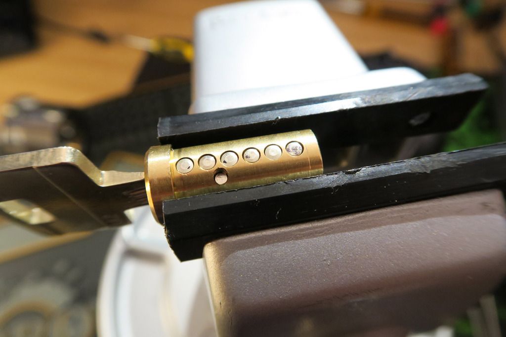
End of the plug:
Pin chambers empty:
Holding the sidebar in. This interacts with the side-pins (which in turn are interacted with by the key) and like most sidebar locks, the sidebar will stick out when the correct key is not inserted:
Photographing this was a nightmare as I don’t have a proper macro lens. You’re looking at the slot where the sidebar goes – I’ve removed it for this shot – and inside the slot you’re looking at the side of the side pins. The little serrations you see are where the sidebar nubs fit into:
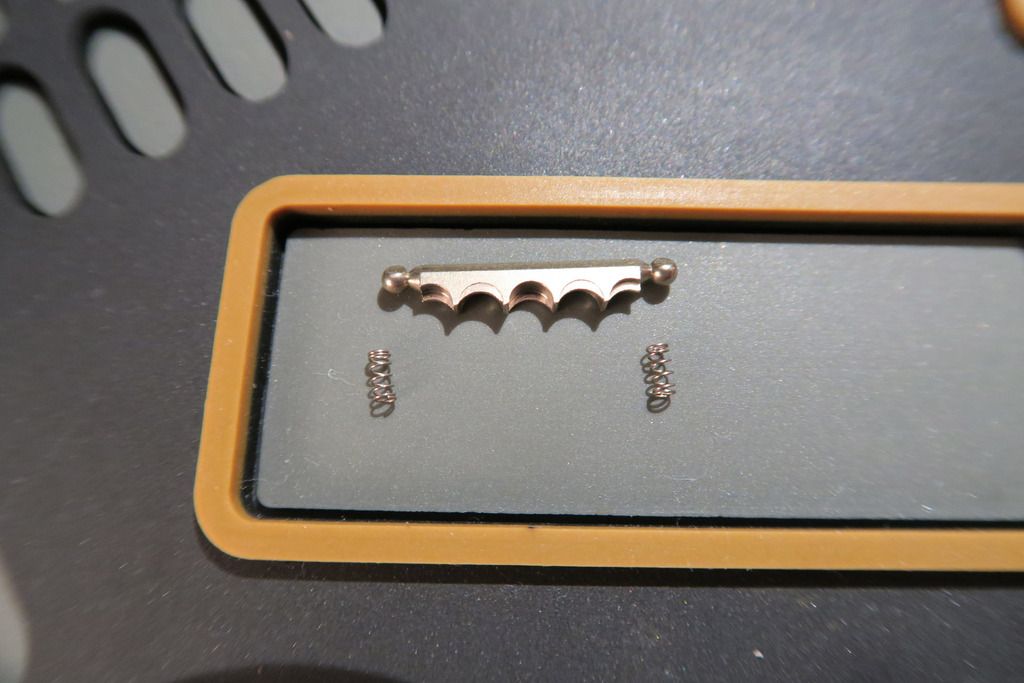
Sidebar and springs, which are SUPER TINY and will fly off at high speed when you’re trying to fit the sidebar under tension, and will get lost on the floor forcing you to spend an hour hunting for them. Twice. So I hear... ¬_¬
The side pins have a higher edge and a lower edge, which interacts with the cuts on the key. I’ve not got it PERFECTLY worked out like the Medeco system but I have a rough idea of how it works...
The key does thankfully keep the side pins in place, so when you’ve managed to finagle the pins down into their chambers and slid the key over the top, they won’t leave in a hurry.
Show of the sidepins and springs. So, add that to the list of parts that come out of this lock! Interestingly there are six primary pins but only five sidebar pins:
A couple of attempted close-ups (like I said, no decent macro lens...) of the side pins. Note the notch cut into the side for the sidebar nubs to fit into:
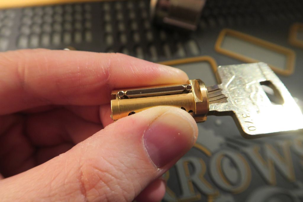
The plug with all the “bits” removed. There’s barely anything left of it!!
All the parts – as before, but now including the side pins, springs, sidebar & springs, plug, body and key. Phew!
Time to re-assemble! First, drop in the sidebar springs and pins, then carefully rotate the side pins to the right angle, push them down and slide the key over the top (may take some fiddling) until the key fits all the way in:
(Quick note: No, actually, the first step is to load the damn armoured front plate into the key FIRST – ideally onto the plug, but it WILL keep slipping off. However it’s a gigantic pain in the arse to try and fit this after the plug has been assembled...)
Next step: Load the key pins and master wafers. If you don’t have any master wafers, you can skip this step and load them from the lock body along with the drivers (master wafers tend to get stuck inside the chamber in my experience):
Then, C.A.R.E.F.U.L.L.Y load the tiiiny springs into the cutouts for them in the sidebar slot, and then add the sidebar. Test it goes down all the way, then curse and have to take the sidebar back out, locate and re-insert the springs that just pinged off everywhere, and reinsert the sidebar the other way round ‘cos you put it on back to front....:
You can then hold the sidebar in and load the plug back into the lock body. Little tip – stick some tape over the pin chambers on the outer body to stop the key pins and wafers leaving while you re-attach the actuator:
Now it’s very important that you attach the actuator – otherwise the plug will fall out and key pins, master wafers, sidebar & springs, key pins and springs will fly EVERYWHERE. Be careful when screwing it back in as it’s easy to push the plug out with the force of the screwing motion – I recommend using a vice and jamming it in in such a way that the plug cannot leave:
For some reason, I didn’t get any photos of the next step. Anyway, once the actuator is screwed on, carefully remove the tape (dropping any master wafers and pins that may be stuck – be careful as they can get caught in the chambers), and refill the pin chambers with driver pins and springs. Then load the bar into the hole in the back and use the trick I mentioned earlier to get it pushed through. Then simply screw it back into place and BOOM, you’re done.
This is definitely one of my coolest finds and I hope to get it mounted in a stand of some kind to show off properly
. Thanks for following my journey!