


![]() Mon Sep 02, 2013 11:24 am
Mon Sep 02, 2013 11:24 am
DOM Diamont Teardown - warning - very picture heavy!!!
DOM Diamont
A tale of two locks. Both mostly the same, but there are some minor differences. The pictures of the first lock were taken about six weeks ago, while the pictures taken of the second lock were a few days ago. For the most part, I am mingling the pictures in this write-up, selecting the best pictures for the description. I do note the differences, and which lock they come from where needed.
This first one was sent to me by an Aussie who had a "weird lock with a funny key" that barely worked. He did not have a picture, but told me it said "WOD" on the lock. He tossed it in with a trade, asking if I could figure it out. I supposed it was just some strange Aussie lock.
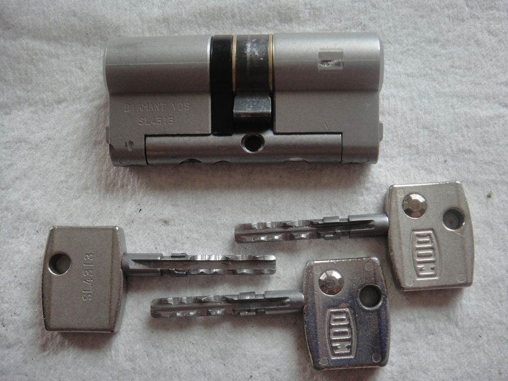
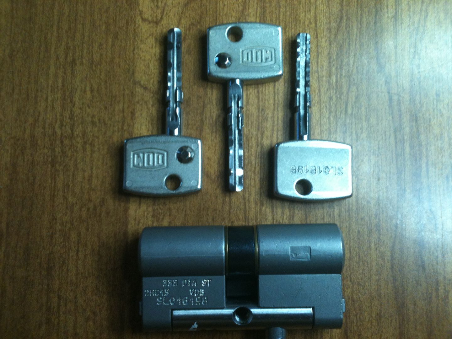
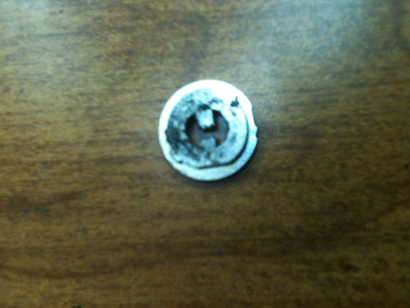
When the box was opened, here was his "WOD". NOTE: This picture was taken after the lock had been disassembled and cleaned.
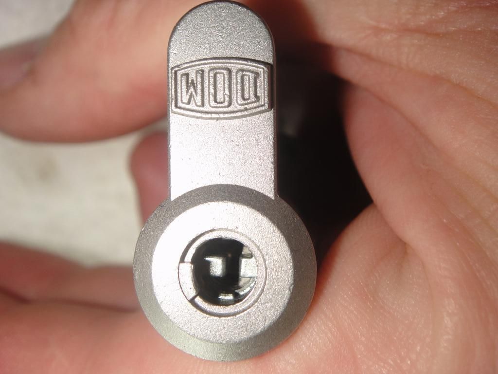
 So his "WOD" was a DOM. Diamont, to be more accurate.
So at long last, I had my grubby little paws on a Diamont.
Now, a month or so later, have another one from ARF-GEF! Slightly different. The locks differ in several ways. Most of the differences have to do with the parts relevant to the longer lock. This new (well, more recently received) one is shorter, made for a thinner door.
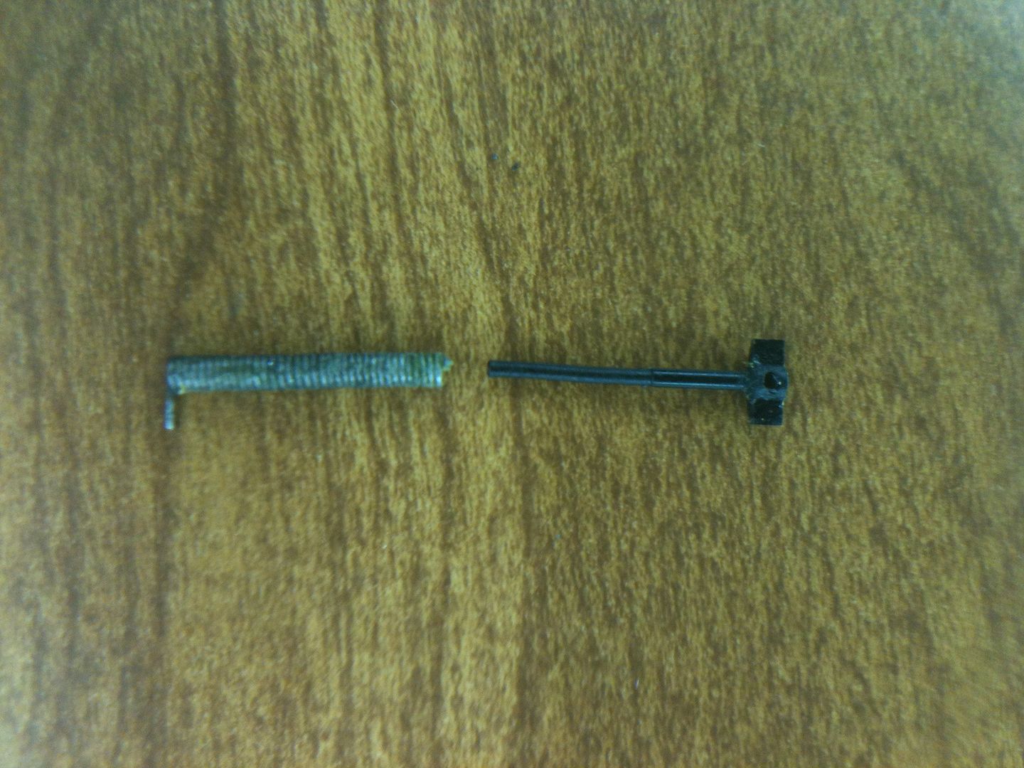
There is a spacer, with a longer top bar on the first one, and another screw to hold the spacer in place...
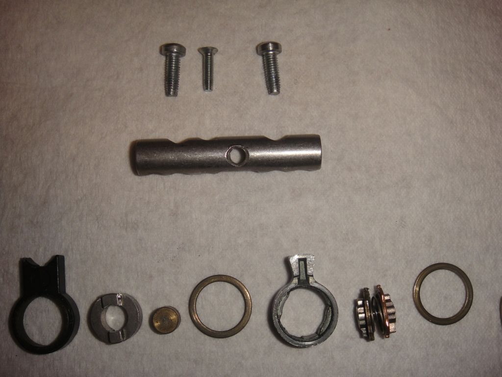
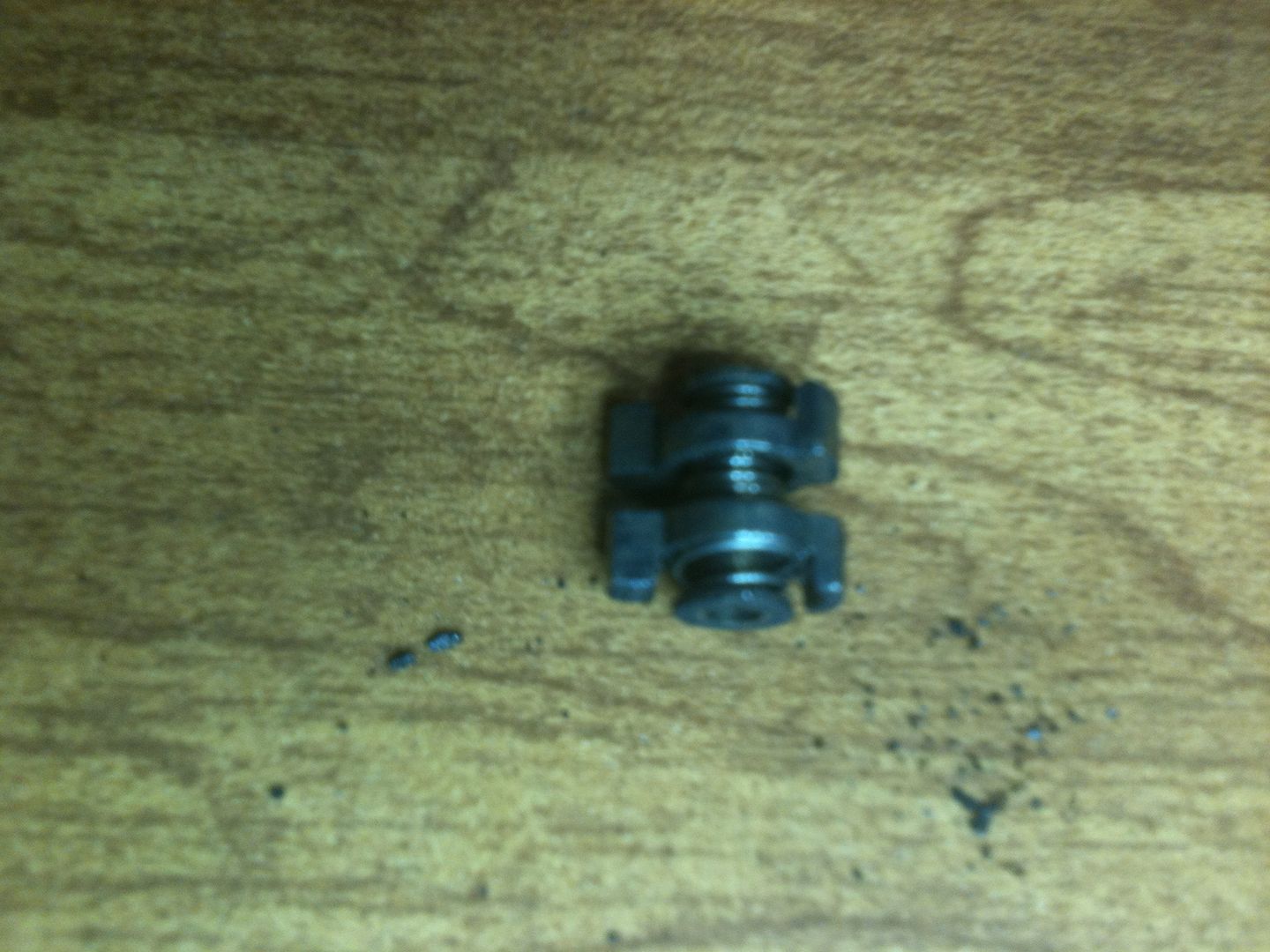
The actuator for the cam is different...
(first one) notice that one side has a brass spacers the other side is copper.
(second one)
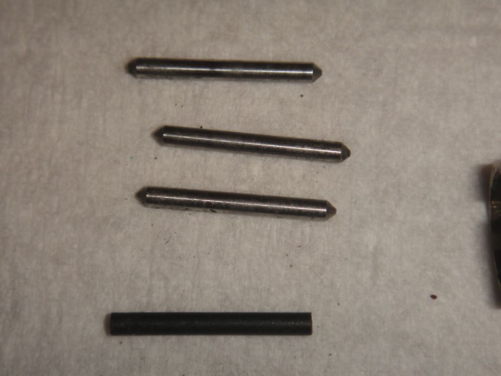
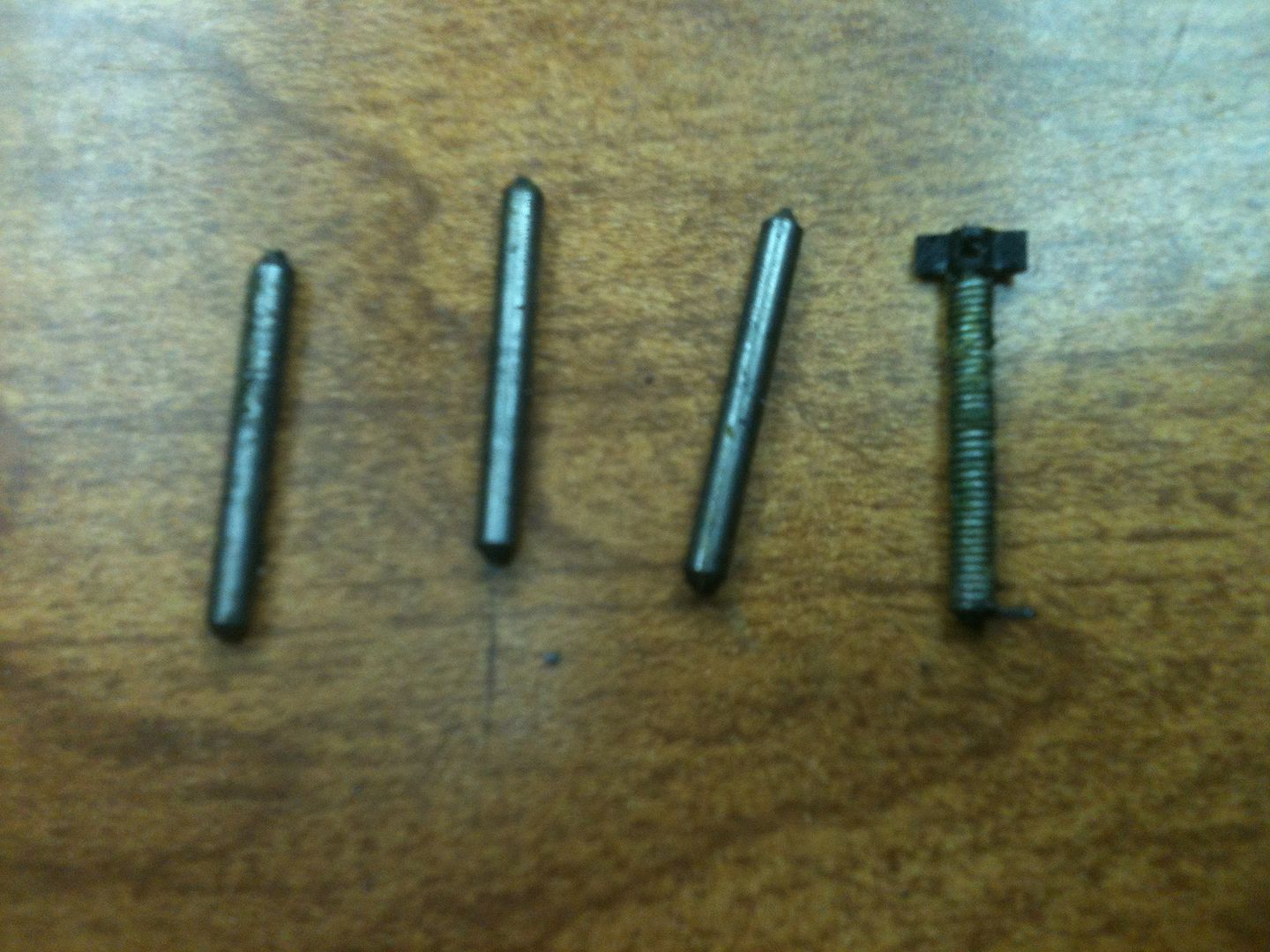
The related components for the extension on the first lock are not found in the second lock. (The three components on the left in this picture)...
And the damper bar is different:
The first one uses a rubber 'side bar' at the bottom:
The second lock uses a much more intricate spring over plastic bar:
Now for the tear-down. Will not dwell on the differences between the WOD lock and the DOM lock. Most of the remaining parts, as well as the breakdown process, are the same.
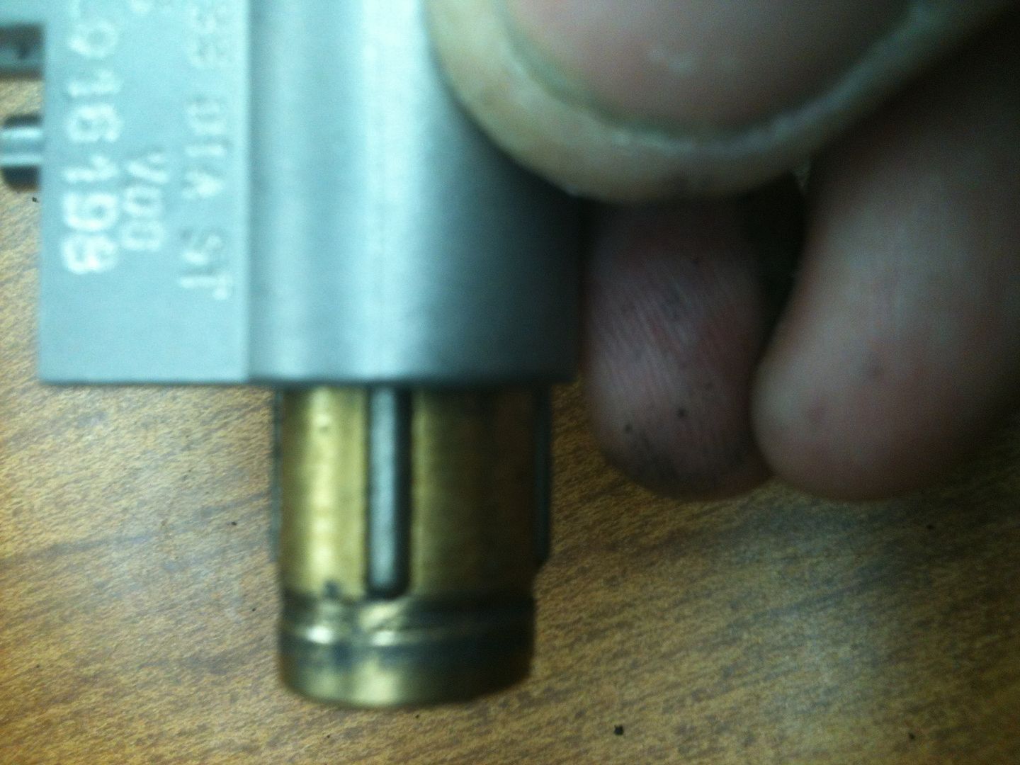
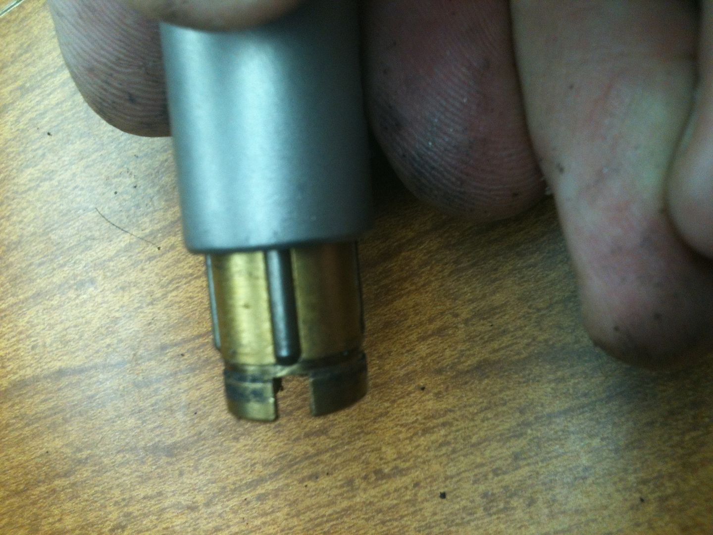
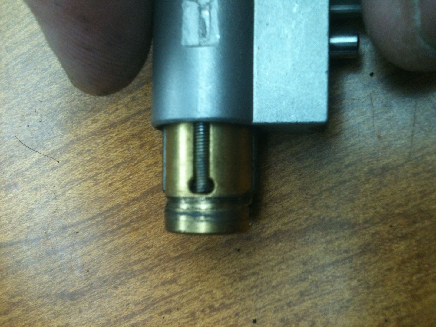
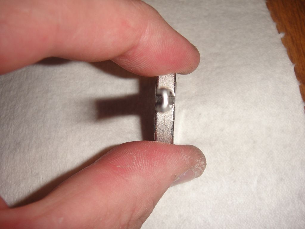
Remove these screws at the bottom of the cylinder.
The proper tool is a Torx T20 driver The lock with the spacer added also uses a Torx T15 to remove the screw in the spacer.
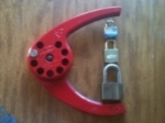
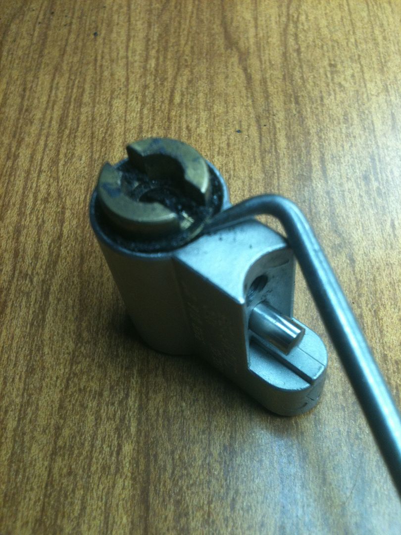
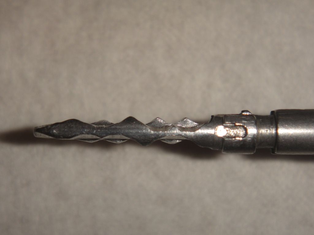
Or if it is stuck, a set up like this pops it loose easily:
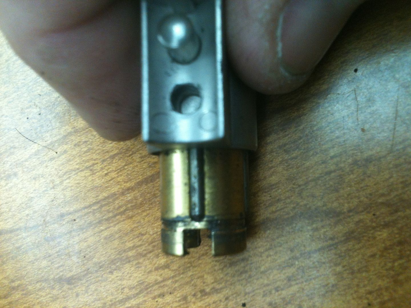
Remove the bar. The cam, washers, actuator, and the two cylinders now will separate. On the lock with the extended center section, pay attention and note the direction the cam actuator (the part with the spring) is facing. Trust me, it will save time with reassembly. Especially with the WOD.
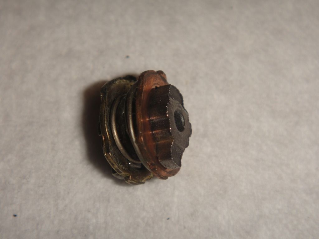
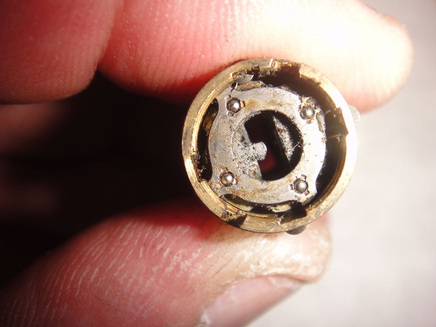
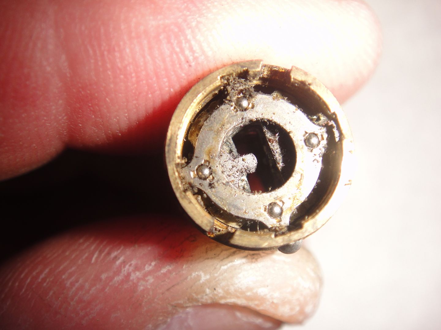
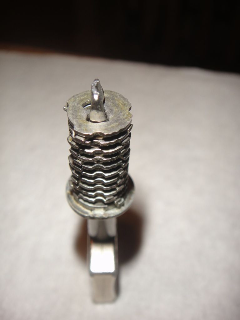
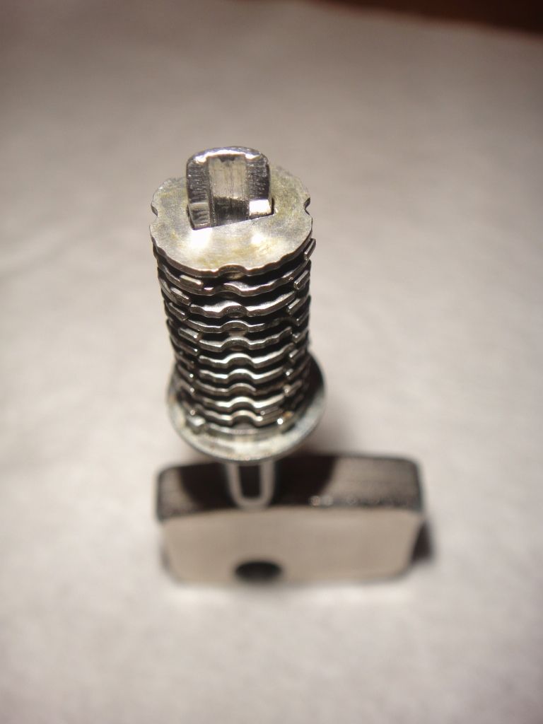
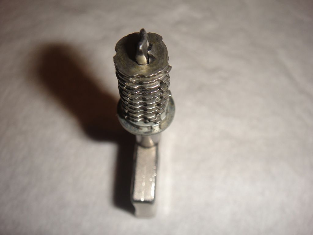
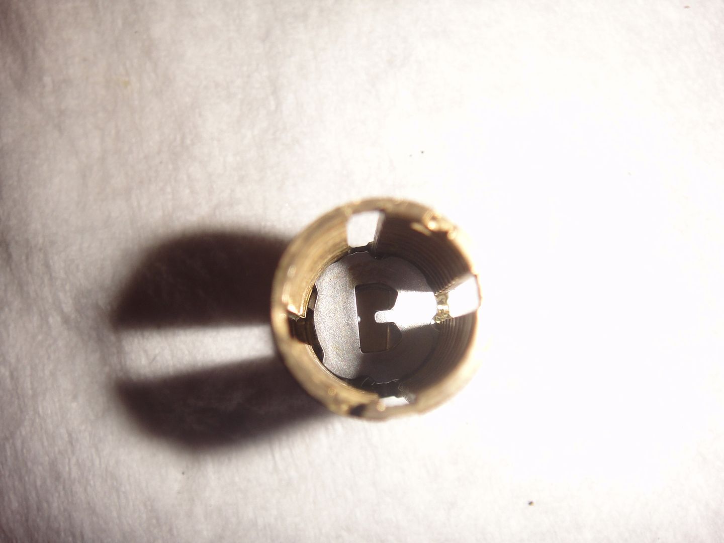
Holy Moley! Can anybody guess why this lock had so much trouble getting the key to enter fully? (This one is the lock from ARF-GEF, but the other one was just as bad.)
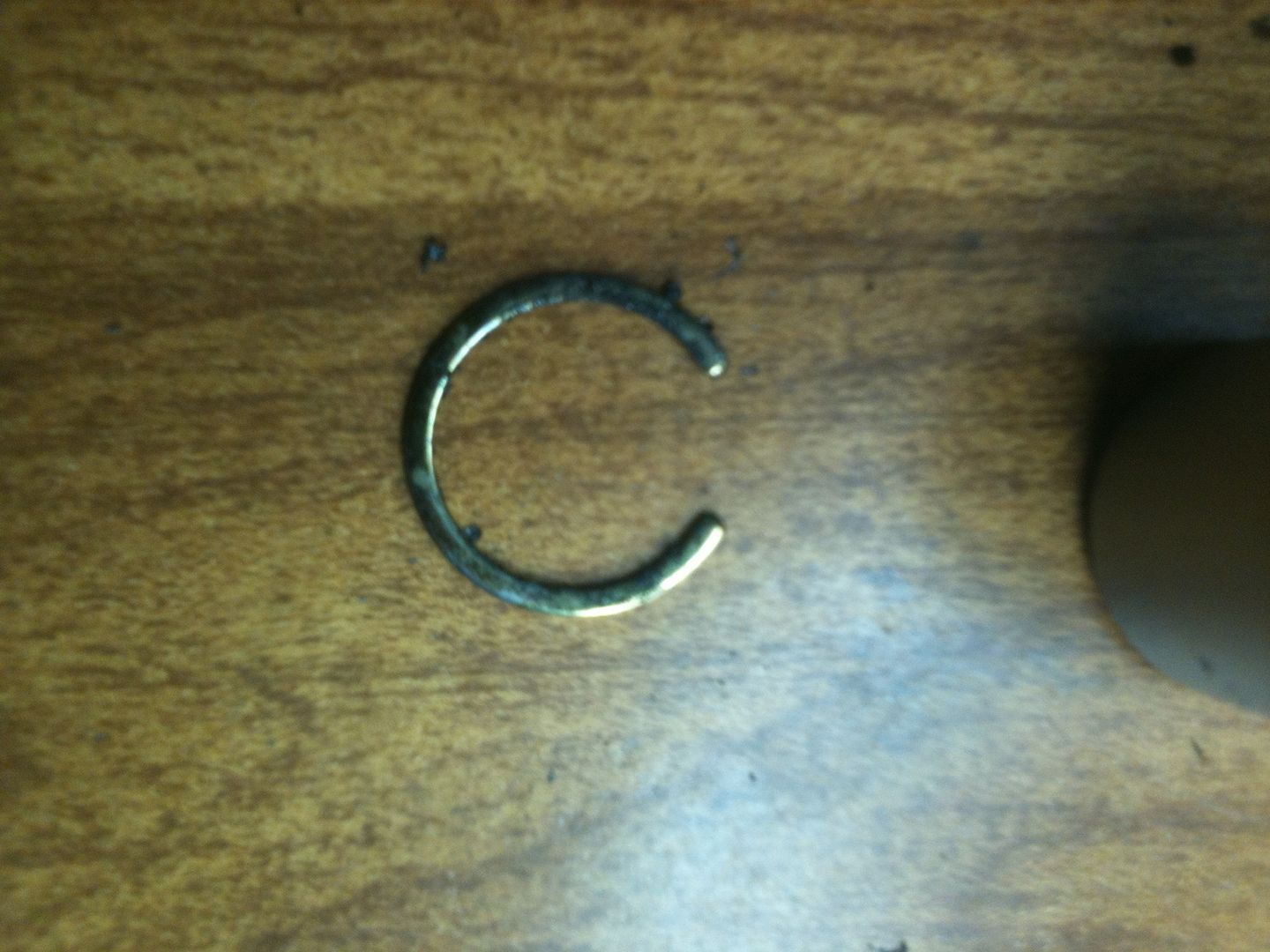
Remove the clip...
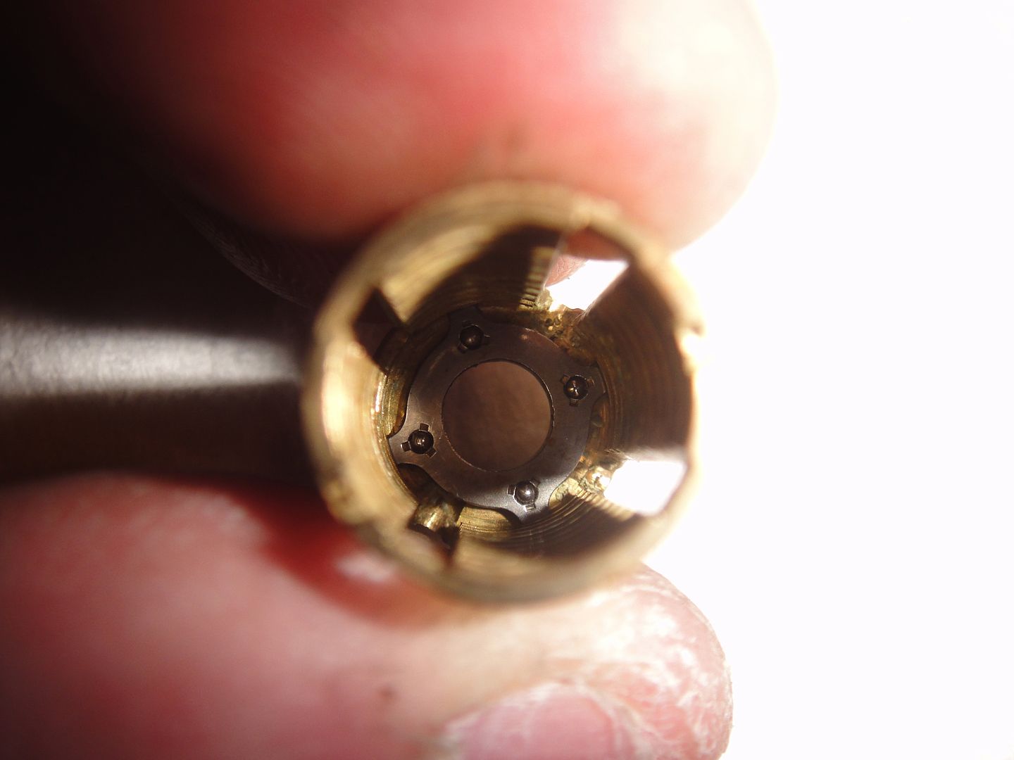
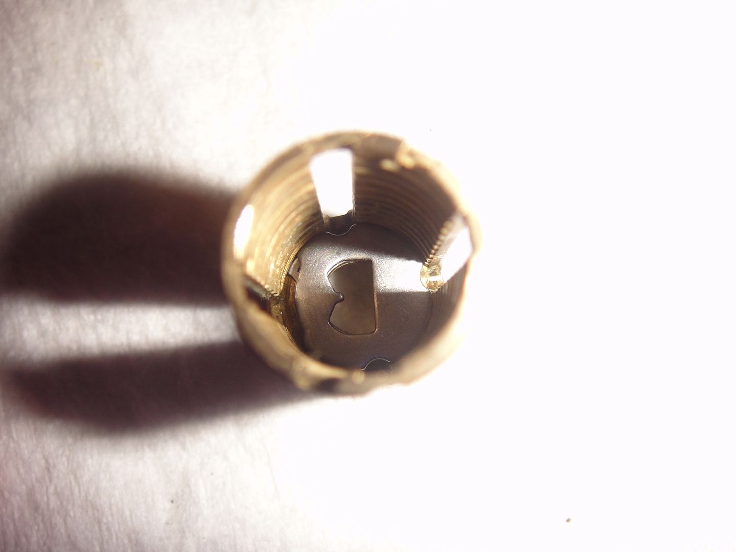
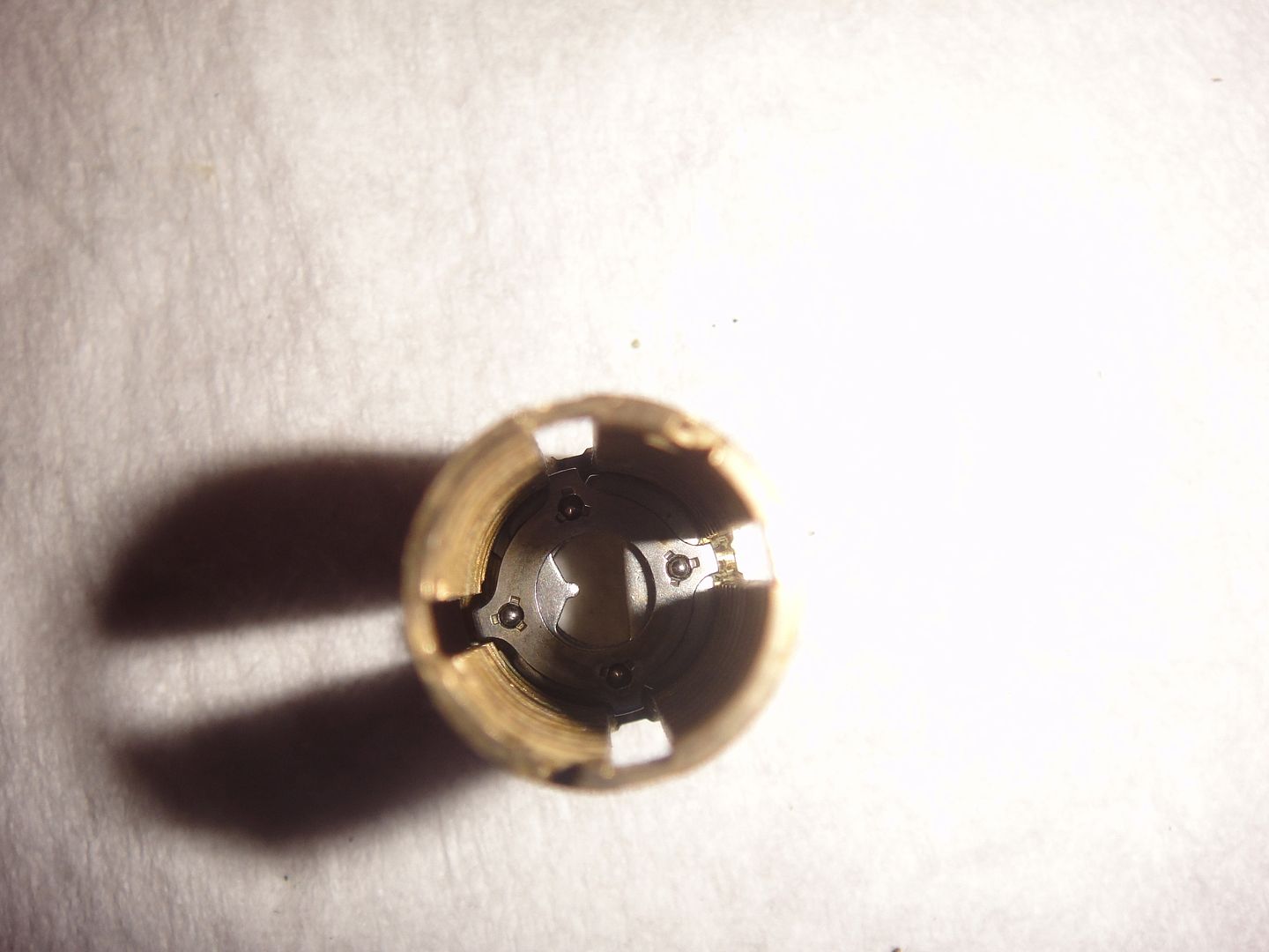
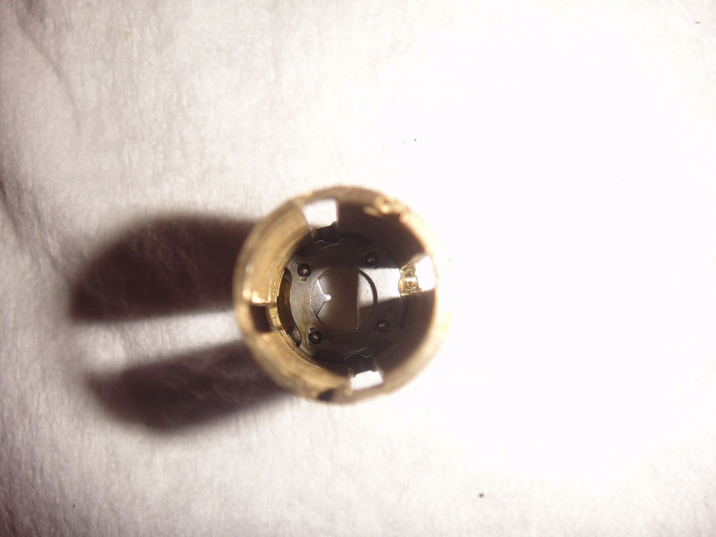
Now start to slide out the carrier. Like an ABLOY, this lock has the discs and spacers stacked inside a carrier, though that is close to where the similarity ends. The following four pictures show the left, top, right, and bottom sides of the carrier as it is being removed. This is so you can see the three sidebars and the damper in place.
The damper, located on the right side of the lock with these euro profile locks properly mounted:
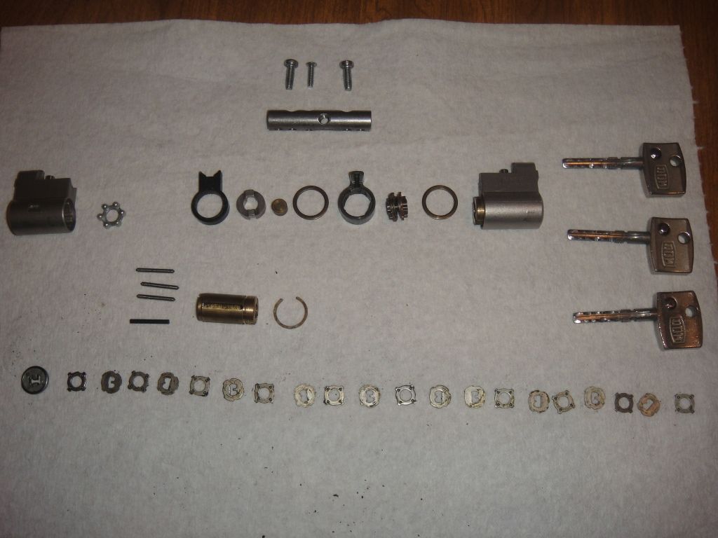
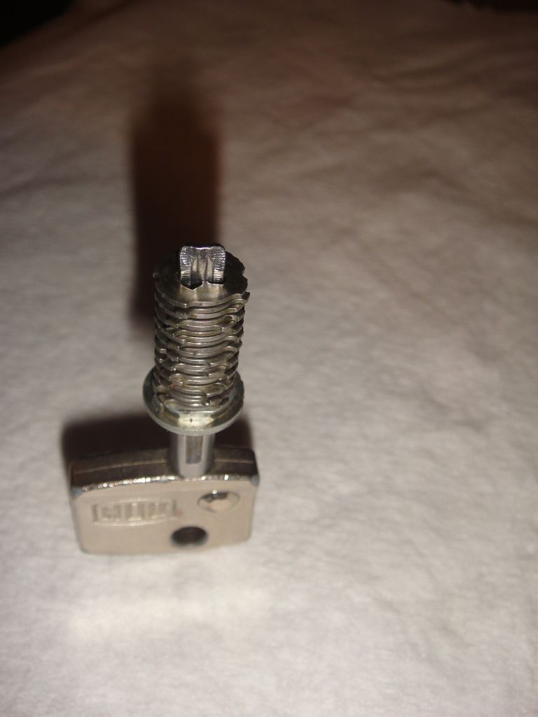
The contents of the cylinder removed from the cylinder.
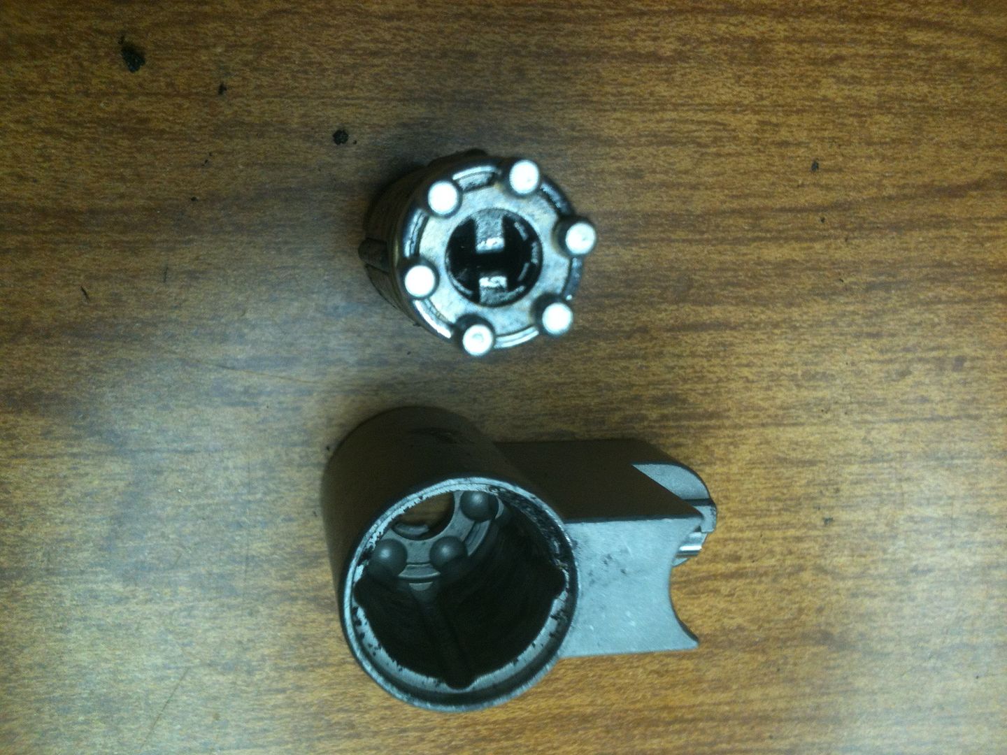
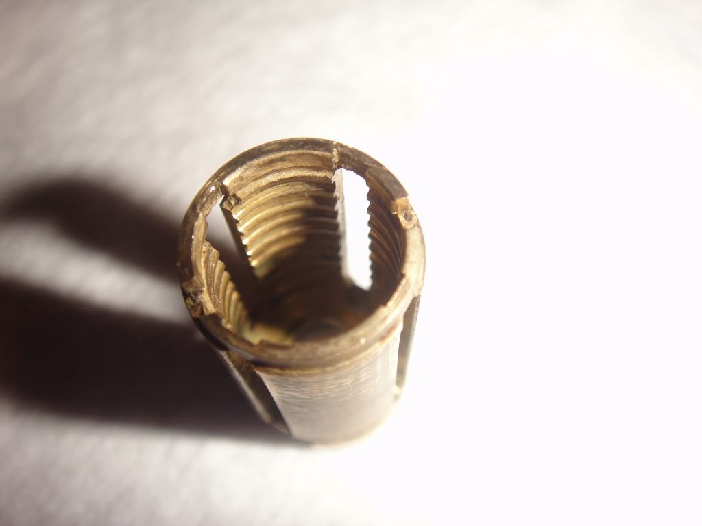
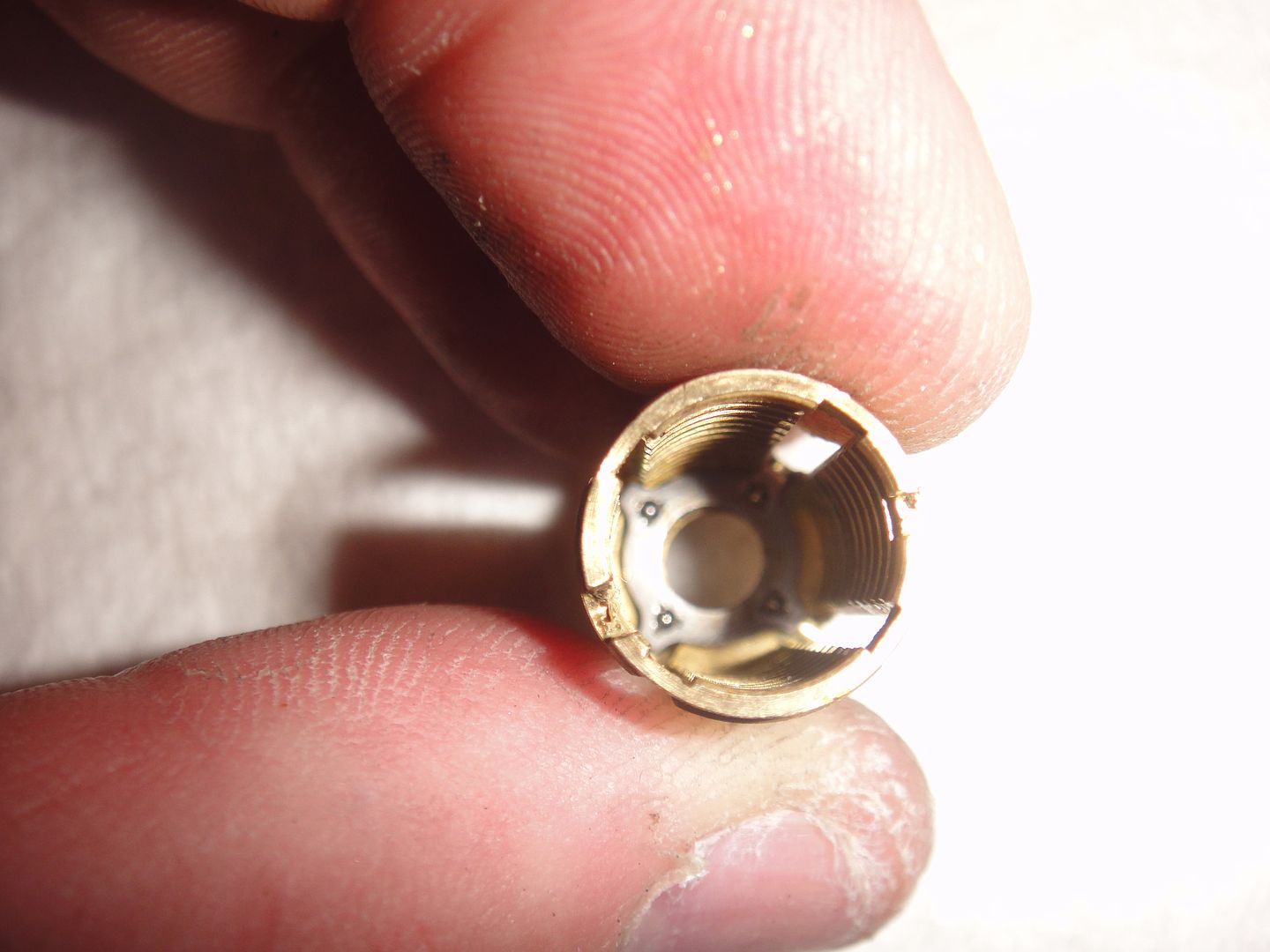
The empty cylinder. You can see the three groves for the three side bars. The damper goes against the smooth part of the bore.
The divots at the front of the bore (where the key enters) are to hold this anti-drill spacer:
There are four slots in the carrier. Three are straight and hold the side bars.
And the fourth is for the damper, which is added to reduce feedback from picking.
On the first lock, it is just "I" shaped
On the second lock, one end of the "I" is milled down a bit for the plastic head to fit flush into the carrier.
Now remove the profile disc. This disc does not turn at all, it has tabs on the other side that lock into the carrier. Note the full shape of the milling on the inside. Part of the key shaft next to the bow has small millings to fit this profile. A key with a different profile will fit almost all the way in, but not quite, due to this profile disc.
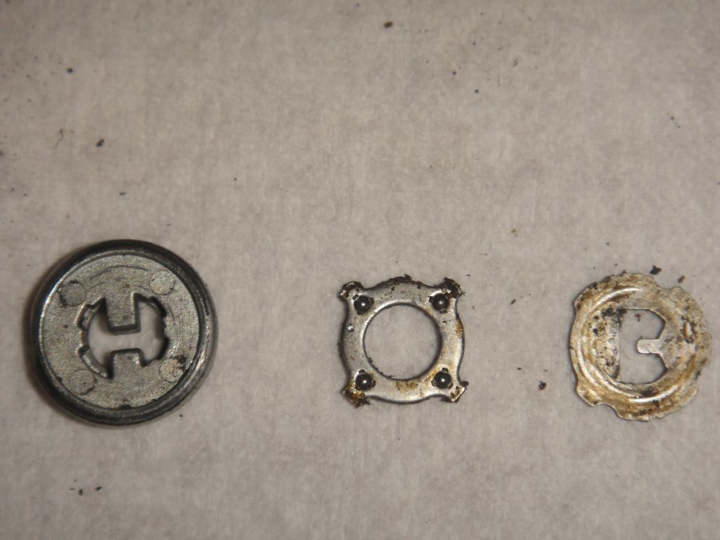
And the inside of the profile disc
Guess I should toss in some pictures of a key. These keys are CNC machined at the factory only. There are five bitting positions, which I will cover shortly.
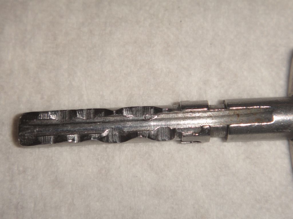
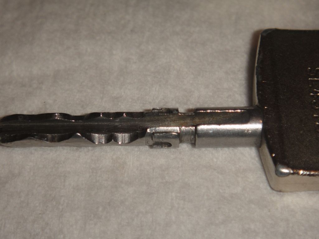
On this picture of a key, you can see that when one side of the key is cut high, the other side is cut low. This has to do with the discs and how they need to rotate as the key is inserted or removed from the lock. More on that when I cover the discs.
And the profile of the key. Note that one side is cut deeper than the other.
Now before I go on to the spacers and discs, am going to skip ahead and show you what the inside of the carrier looks like, as it will help with understanding the disassembly and reassembly of the lock.
There are grooves inside the carrier that each of the spacers lock into. You can also see the slots cut for the profile disc to lock into at the two o'clock and seven o'clock locations.
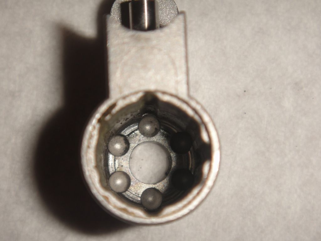
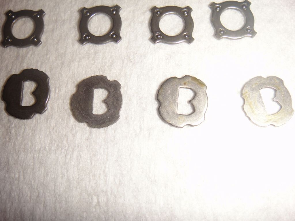
Ok, now for the spacers and discs. Once the profile disc is removed from the carrier, you see the first spacer. Yes, each spacer has four ball bearings to make operation of the discs very smooth. The spacers are locked in the grooves. They can freely turn in the grooves, but the sidebars keep the spacers from turning enough to prevent the spacers from blocking the sidebars, jamming the lock in the locked position.
Here is a spacer locked in position.
And turned so the corners of the spacer line up with the sidebar grooves, allowing the spacer to be removed.
The first disc can be removed, then repeat the process of rotating the next spacer and removing it. Wash, rinse, repeat. Will show more of the pictures of the spacers and discs in the reassembly section below.
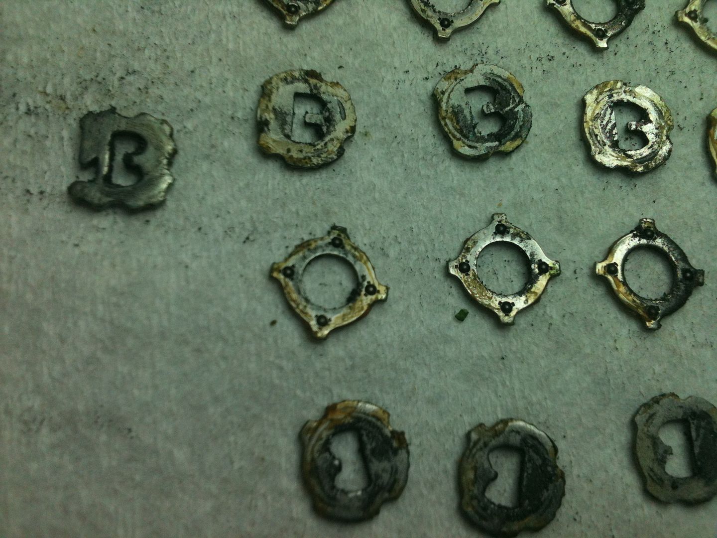
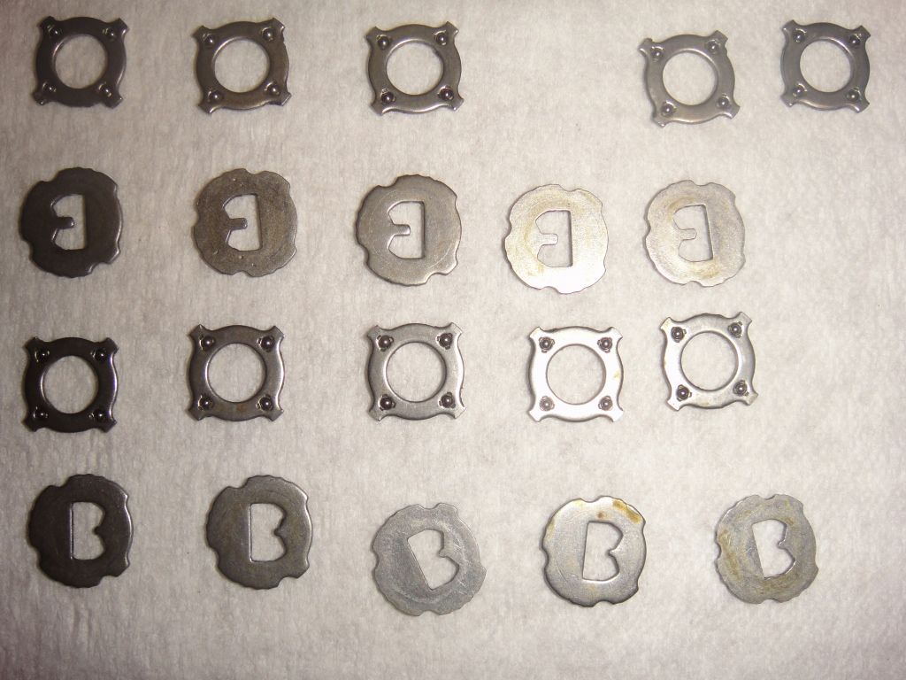
Here the spacers and washers are all laid out, removed from the carrier. As you can see, a little cleaning is in order. The funky disc on the left is the bottom spacer/disc in the lock from ARF-GEF. The extra cut in the side is where the spring from the damper hooks in. The first lock did not have this disc.
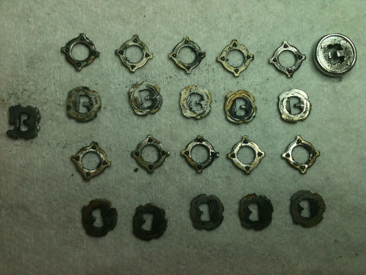
Like I said... A little on the dirty side. This is definitely a major cause of the key insertion/removal problem.
Exploded view of just one side...
Now clean the parts. This is after cleaning just the spacers from one side!
Now you need to reassemble the lock. First, you need to make sure you have the spacers and discs in the correct order. The easiest way I have found (I am not a locksmith, so if you know a better way, let me know, please!) is to use the key, place the profile disc onto it, a spacer, the first disc, spacer, second disc, and so forth until the full disc/spacer pack is loaded onto the key. Hold the key vertically as you go. All the gates should line up on the top, right, and bottom of the key. The big, wide gate should be on the left side of the key.
Notes on the discs. There are five bitting 'depths' for this lock and six discs, not including master discs which I know do exist, but have never seen. The bits are a measure of rotation. The discs will rotate both clockwise and counter-clockwise as the key is inserted and withdrawn. If the disc is not rotated at all in the final key inserted position, then it is a 0 (no rotation). If turned slightly clockwise, it is a 1, more rotation is a 2. If the final rotation is counter-clockwise, then the bittings are -1 and -2.
In this picture, the disc on the far left and the second disc from the right are both facing the same direction. If you look at the bottom edge, you can see the difference in the location of the gates. The first and second discs are the same 'size' disc, but the second one is flipped vertically. This turns a 1 to a -1 or a 2 to s -2. 0 discs are the same either way.
So if three discs can cover all five bittings, why do I say there are six discs? Because you have discs for the left and right sides. Remember the key profile, and how one side is cut deeper? Here is why - the discs have a longer tab on the inside of the "B" one one side than on the other. The longer tab discs go on the right side, pointing towards the left. The shorter tab discs go on the other side.
To reassemble the lock after cleaning out the dirt, place a spacer into the lock. On the lock with the funky disc for the dampener, put it in first. That funky disk also needs to be put in and rotated to lock in space just like the spacers.
Now rotate the spacer to lock it into the first set of grooves.
Add a right disc, which has the shorter "B" tab. The wide open gate is towards the cutout for the damper.
Add the next spacer
And rotate to lock it in place in a groove
Install a left disc
Next spacer, disc, etcetera until the stack is in place.
The rest of the reassembly is the reverse of disassembly.
Questions, comments, and corrections are very much appreciated!
Gordon
A tale of two locks. Both mostly the same, but there are some minor differences. The pictures of the first lock were taken about six weeks ago, while the pictures taken of the second lock were a few days ago. For the most part, I am mingling the pictures in this write-up, selecting the best pictures for the description. I do note the differences, and which lock they come from where needed.
This first one was sent to me by an Aussie who had a "weird lock with a funny key" that barely worked. He did not have a picture, but told me it said "WOD" on the lock. He tossed it in with a trade, asking if I could figure it out. I supposed it was just some strange Aussie lock.
When the box was opened, here was his "WOD". NOTE: This picture was taken after the lock had been disassembled and cleaned.
So at long last, I had my grubby little paws on a Diamont.
Now, a month or so later, have another one from ARF-GEF! Slightly different. The locks differ in several ways. Most of the differences have to do with the parts relevant to the longer lock. This new (well, more recently received) one is shorter, made for a thinner door.
There is a spacer, with a longer top bar on the first one, and another screw to hold the spacer in place...
The actuator for the cam is different...
(first one) notice that one side has a brass spacers the other side is copper.
(second one)
The related components for the extension on the first lock are not found in the second lock. (The three components on the left in this picture)...
And the damper bar is different:
The first one uses a rubber 'side bar' at the bottom:
The second lock uses a much more intricate spring over plastic bar:
Now for the tear-down. Will not dwell on the differences between the WOD lock and the DOM lock. Most of the remaining parts, as well as the breakdown process, are the same.
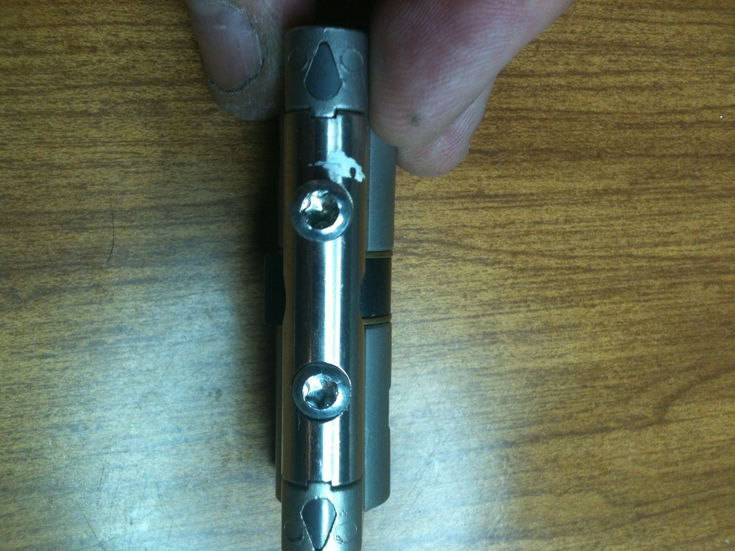
Remove these screws at the bottom of the cylinder.
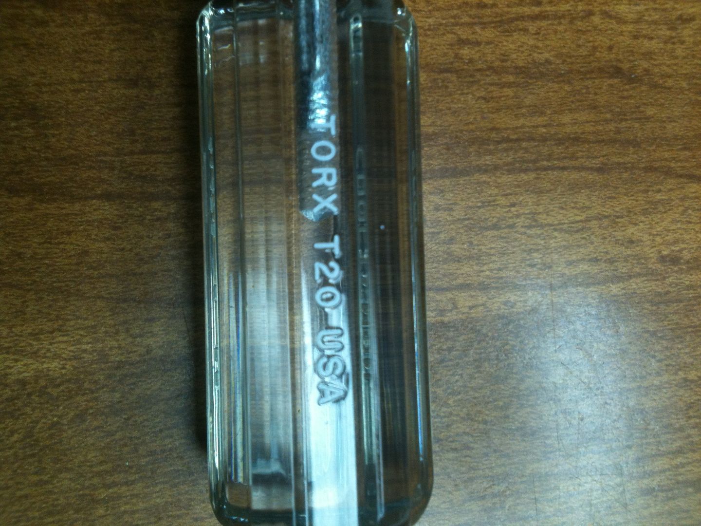
The proper tool is a Torx T20 driver The lock with the spacer added also uses a Torx T15 to remove the screw in the spacer.
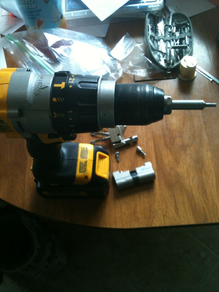
Or if it is stuck, a set up like this pops it loose easily:
Remove the bar. The cam, washers, actuator, and the two cylinders now will separate. On the lock with the extended center section, pay attention and note the direction the cam actuator (the part with the spring) is facing. Trust me, it will save time with reassembly.
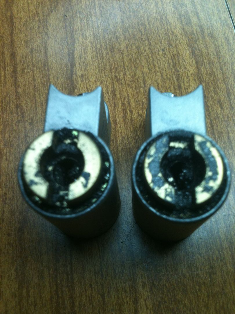
Holy Moley! Can anybody guess why this lock had so much trouble getting the key to enter fully? (This one is the lock from ARF-GEF, but the other one was just as bad.)
Remove the clip...
Now start to slide out the carrier. Like an ABLOY, this lock has the discs and spacers stacked inside a carrier, though that is close to where the similarity ends. The following four pictures show the left, top, right, and bottom sides of the carrier as it is being removed. This is so you can see the three sidebars and the damper in place.
The damper, located on the right side of the lock with these euro profile locks properly mounted:
The contents of the cylinder removed from the cylinder.
The empty cylinder. You can see the three groves for the three side bars. The damper goes against the smooth part of the bore.
The divots at the front of the bore (where the key enters) are to hold this anti-drill spacer:
There are four slots in the carrier. Three are straight and hold the side bars.
And the fourth is for the damper, which is added to reduce feedback from picking.
On the first lock, it is just "I" shaped
On the second lock, one end of the "I" is milled down a bit for the plastic head to fit flush into the carrier.
Now remove the profile disc. This disc does not turn at all, it has tabs on the other side that lock into the carrier. Note the full shape of the milling on the inside. Part of the key shaft next to the bow has small millings to fit this profile. A key with a different profile will fit almost all the way in, but not quite, due to this profile disc.
And the inside of the profile disc
Guess I should toss in some pictures of a key. These keys are CNC machined at the factory only. There are five bitting positions, which I will cover shortly.
On this picture of a key, you can see that when one side of the key is cut high, the other side is cut low. This has to do with the discs and how they need to rotate as the key is inserted or removed from the lock. More on that when I cover the discs.
And the profile of the key. Note that one side is cut deeper than the other.
Now before I go on to the spacers and discs, am going to skip ahead and show you what the inside of the carrier looks like, as it will help with understanding the disassembly and reassembly of the lock.
There are grooves inside the carrier that each of the spacers lock into. You can also see the slots cut for the profile disc to lock into at the two o'clock and seven o'clock locations.
Ok, now for the spacers and discs. Once the profile disc is removed from the carrier, you see the first spacer. Yes, each spacer has four ball bearings to make operation of the discs very smooth. The spacers are locked in the grooves. They can freely turn in the grooves, but the sidebars keep the spacers from turning enough to prevent the spacers from blocking the sidebars, jamming the lock in the locked position.
Here is a spacer locked in position.
And turned so the corners of the spacer line up with the sidebar grooves, allowing the spacer to be removed.
The first disc can be removed, then repeat the process of rotating the next spacer and removing it. Wash, rinse, repeat. Will show more of the pictures of the spacers and discs in the reassembly section below.
Here the spacers and washers are all laid out, removed from the carrier. As you can see, a little cleaning is in order. The funky disc on the left is the bottom spacer/disc in the lock from ARF-GEF. The extra cut in the side is where the spring from the damper hooks in. The first lock did not have this disc.
Like I said... A little on the dirty side. This is definitely a major cause of the key insertion/removal problem.
Exploded view of just one side...
Now clean the parts. This is after cleaning just the spacers from one side!
Now you need to reassemble the lock. First, you need to make sure you have the spacers and discs in the correct order. The easiest way I have found (I am not a locksmith, so if you know a better way, let me know, please!) is to use the key, place the profile disc onto it, a spacer, the first disc, spacer, second disc, and so forth until the full disc/spacer pack is loaded onto the key. Hold the key vertically as you go. All the gates should line up on the top, right, and bottom of the key. The big, wide gate should be on the left side of the key.
Notes on the discs. There are five bitting 'depths' for this lock and six discs, not including master discs which I know do exist, but have never seen. The bits are a measure of rotation. The discs will rotate both clockwise and counter-clockwise as the key is inserted and withdrawn. If the disc is not rotated at all in the final key inserted position, then it is a 0 (no rotation). If turned slightly clockwise, it is a 1, more rotation is a 2. If the final rotation is counter-clockwise, then the bittings are -1 and -2.
In this picture, the disc on the far left and the second disc from the right are both facing the same direction. If you look at the bottom edge, you can see the difference in the location of the gates. The first and second discs are the same 'size' disc, but the second one is flipped vertically. This turns a 1 to a -1 or a 2 to s -2. 0 discs are the same either way.
So if three discs can cover all five bittings, why do I say there are six discs? Because you have discs for the left and right sides. Remember the key profile, and how one side is cut deeper? Here is why - the discs have a longer tab on the inside of the "B" one one side than on the other. The longer tab discs go on the right side, pointing towards the left. The shorter tab discs go on the other side.
To reassemble the lock after cleaning out the dirt, place a spacer into the lock. On the lock with the funky disc for the dampener, put it in first. That funky disk also needs to be put in and rotated to lock in space just like the spacers.
Now rotate the spacer to lock it into the first set of grooves.
Add a right disc, which has the shorter "B" tab. The wide open gate is towards the cutout for the damper.
Add the next spacer
And rotate to lock it in place in a groove
Install a left disc
Next spacer, disc, etcetera until the stack is in place.
The rest of the reassembly is the reverse of disassembly.
Questions, comments, and corrections are very much appreciated!
Gordon
Just when you think you've learned it all, that is when you find you haven't learned anything yet.