


![]() Sun Aug 25, 2013 9:12 am
Sun Aug 25, 2013 9:12 am
Ingersoll Invincible Padlock Teardown
Ingersoll Invincible Padlock Teardown
The Ingersoll locks are pretty cool lever locks with a sidebar. Have not yet succeeded in picking this lock with the rubber o-ring (bushing) installed.
For more information on the key for this lock, see 10Ringo10's topic
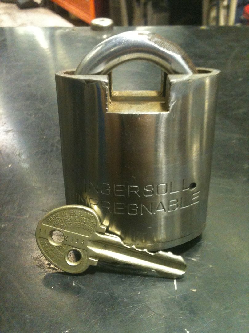
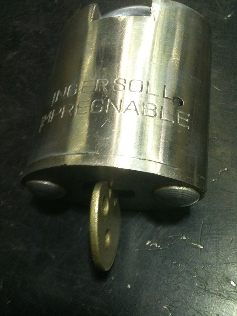
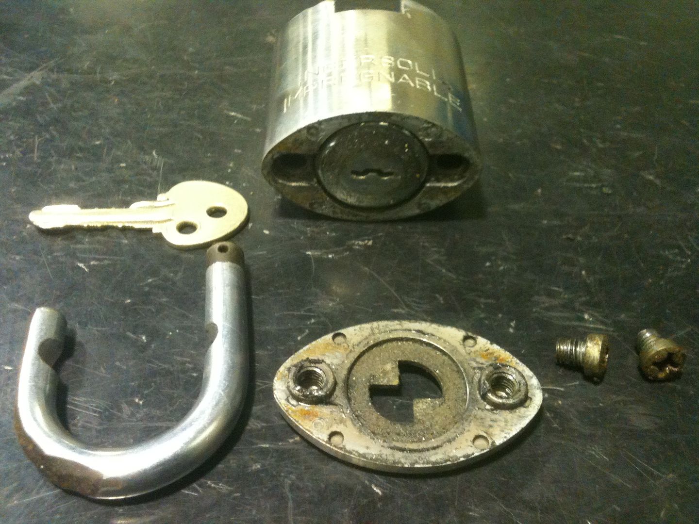
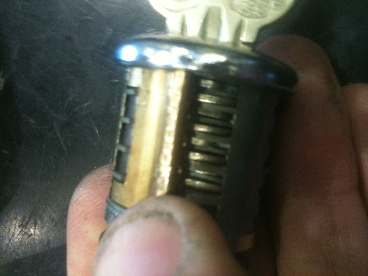
Here is the lock with the key:
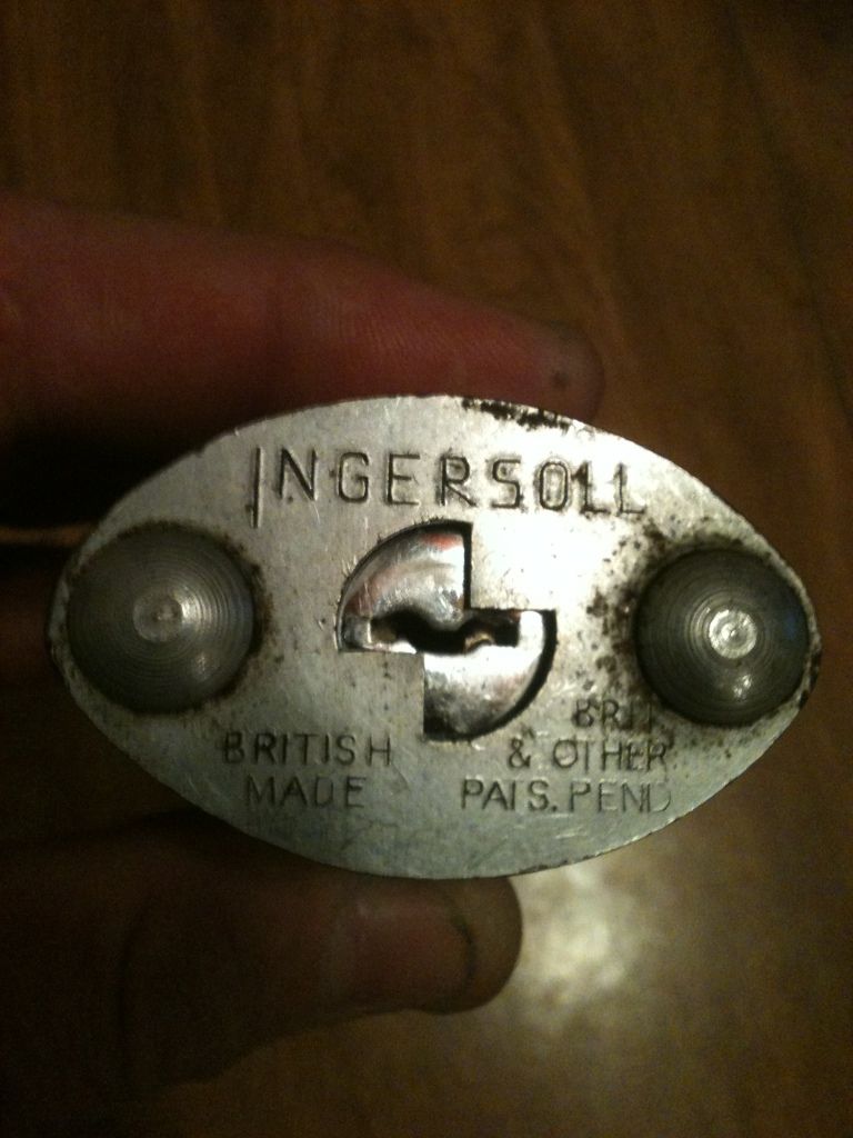
And the keyway
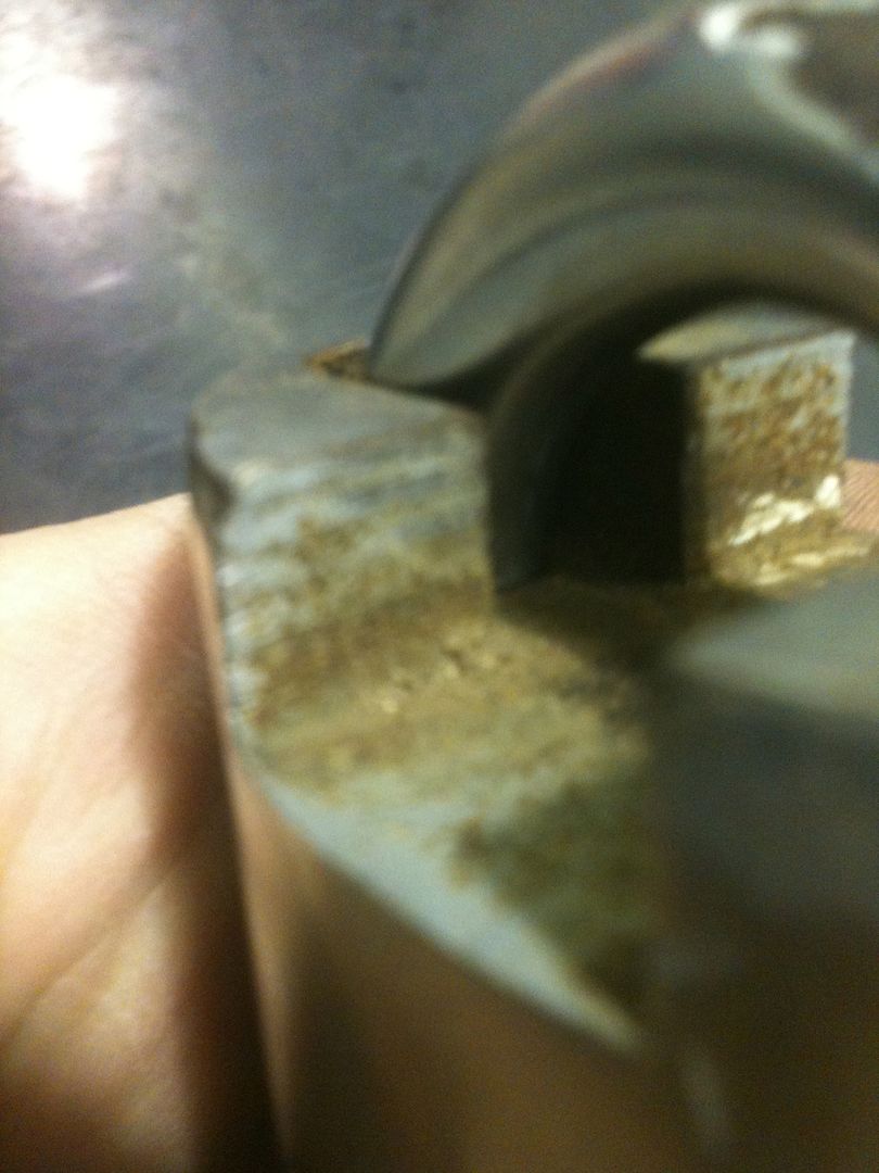
Even though the lock body looks solid, it is a laminated lock, making it very strong. You can see the laminations in the area milled for the shackle area.
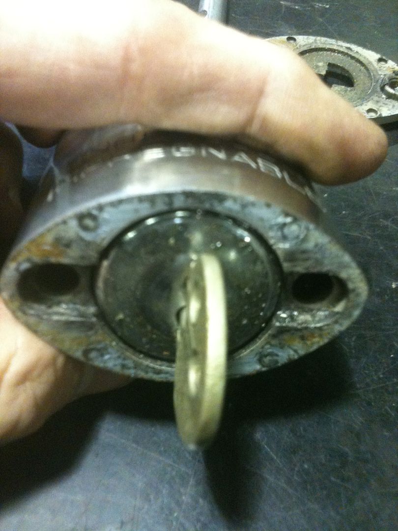
Now for the teardown. First, insert the key and turn it like so:
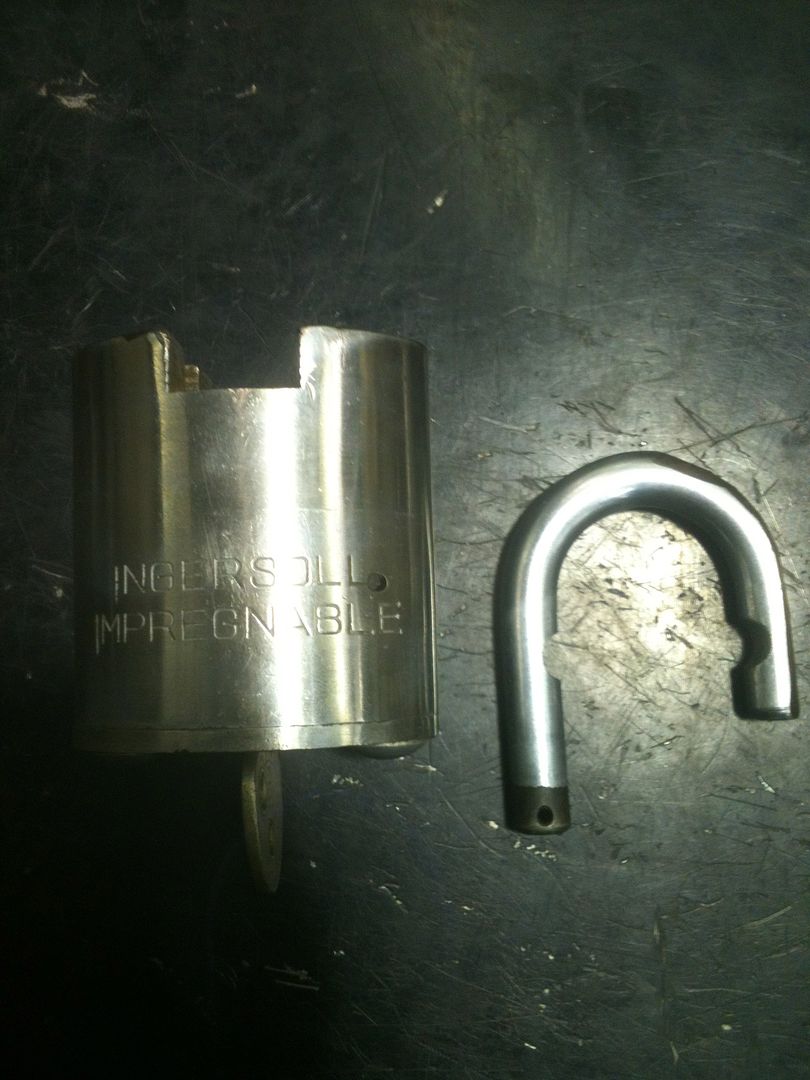
On my lock, the shackle comes out at this point. As has been told to me, the shackle should not come out, so something must be missing that fits through the hole at the bottom of the shackle.
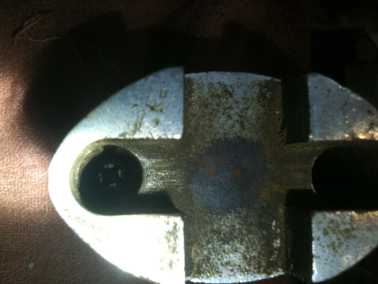
Inside the shackle holes, you can see the Phillips screws. These are very large screws. You need a P3 size screwdriver.
Remove the key, then the screws, and cover plate.
Put the key back into the cylinder and turn it to the unlocked position.
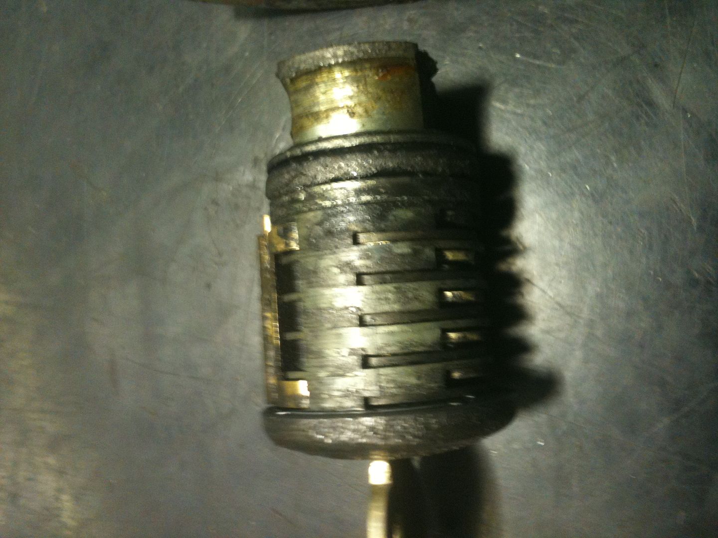
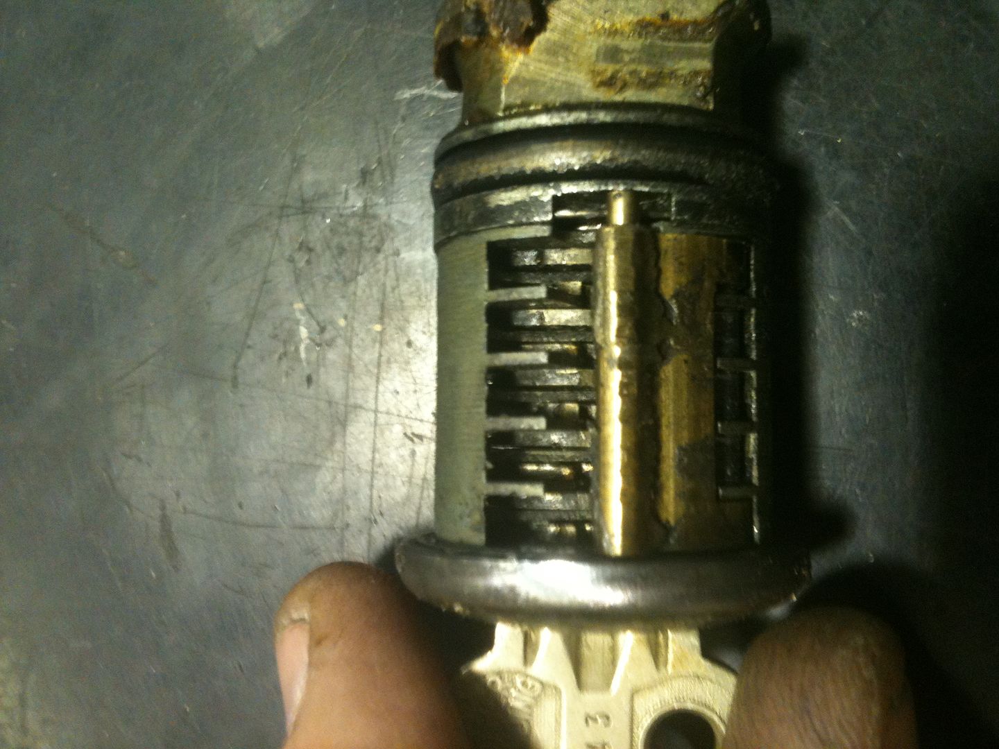
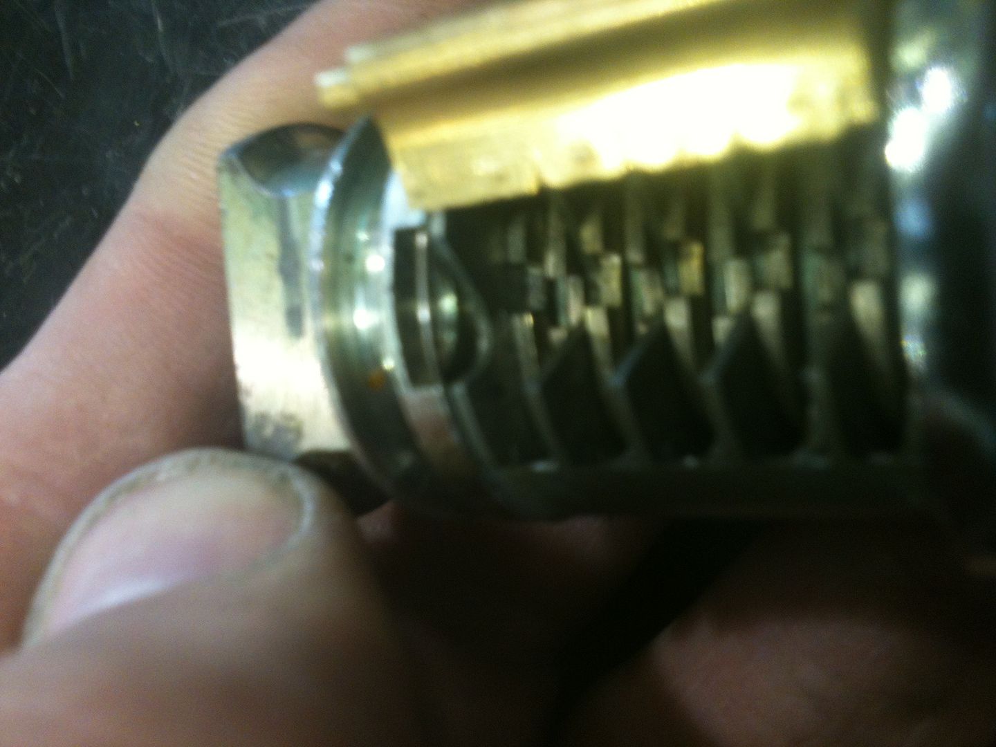
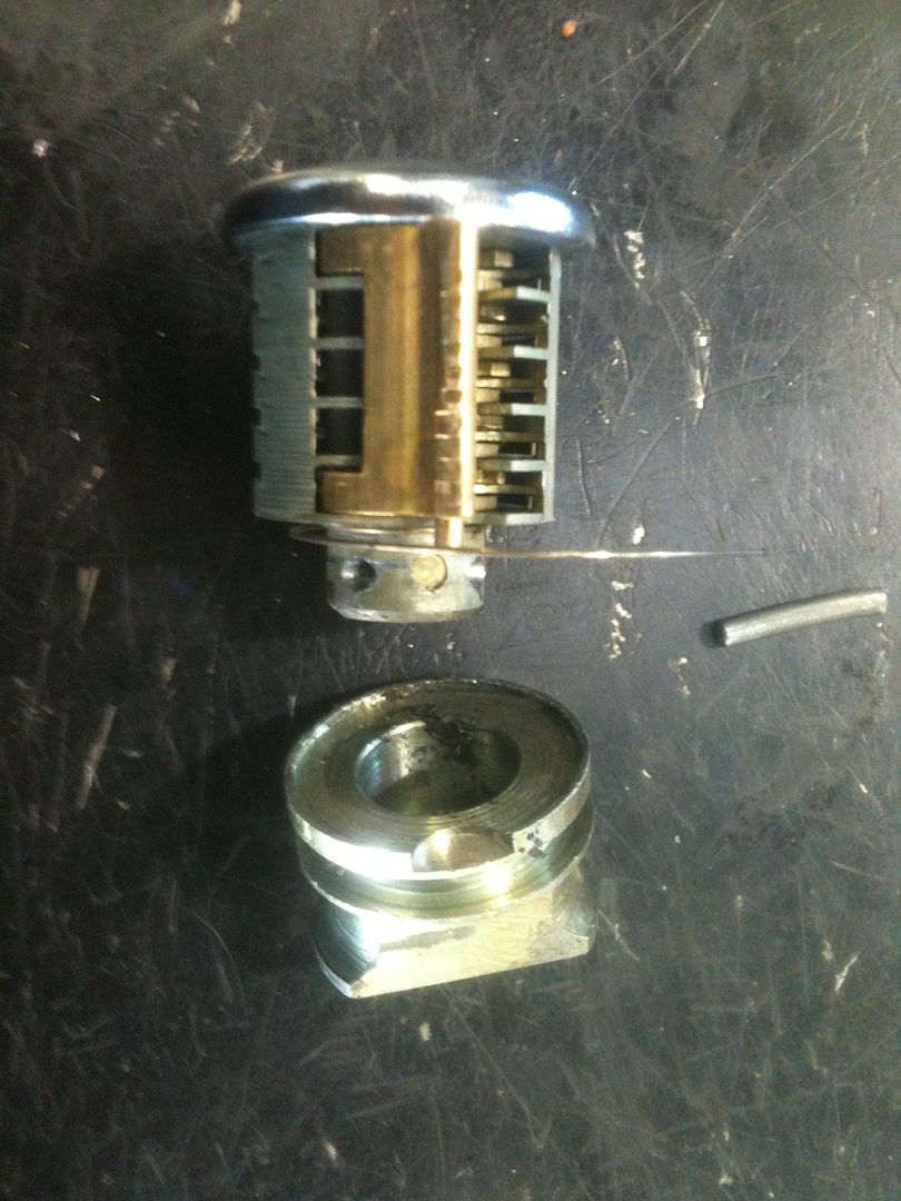
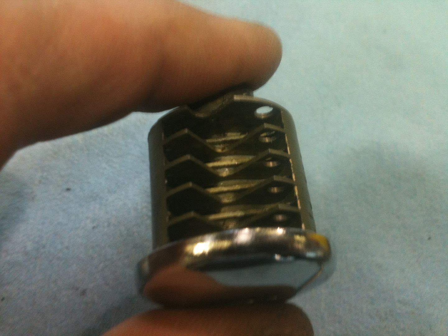
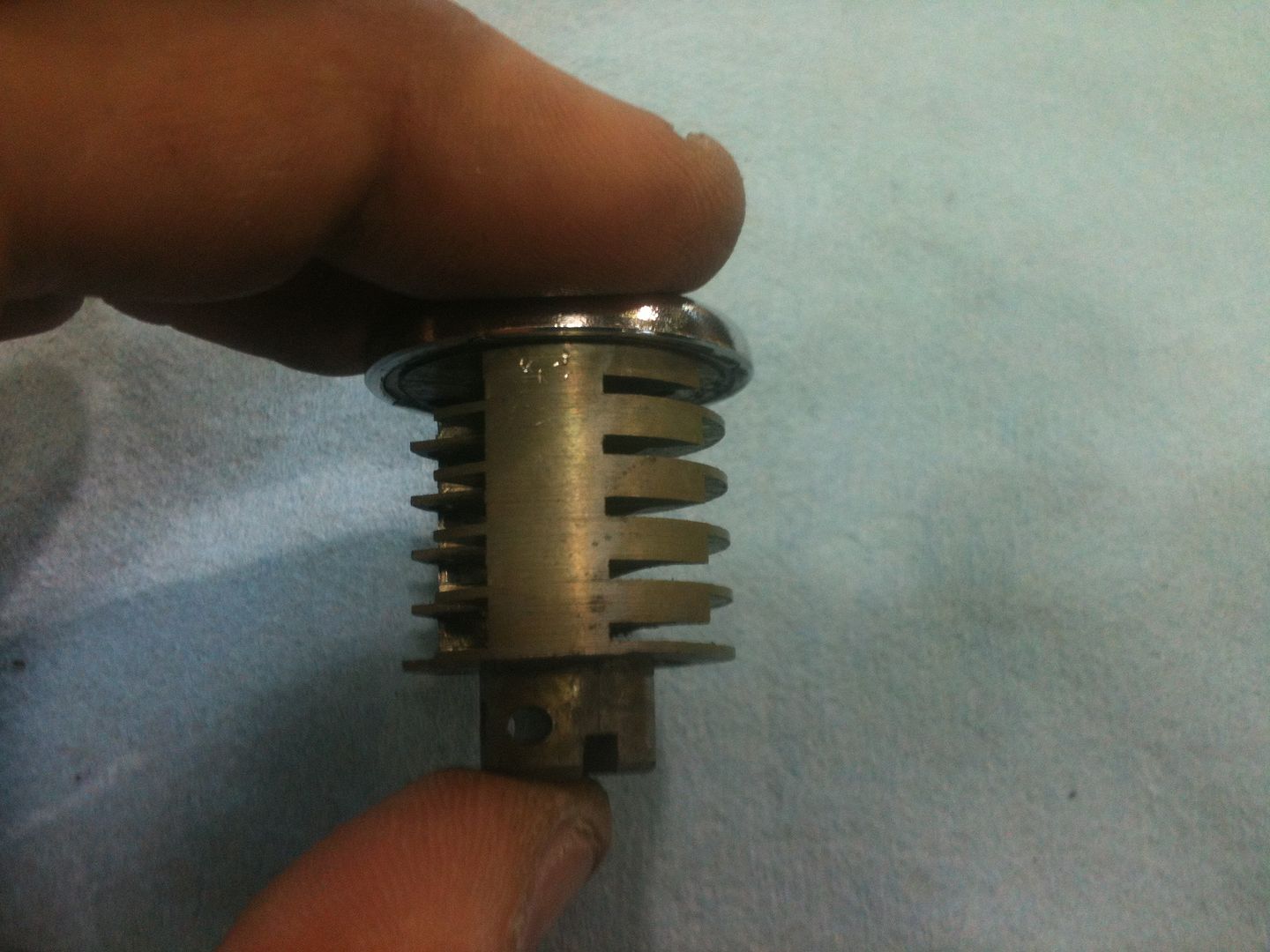
The plug can now be removed by pulling the key. As you can see, this particular lock has plenty of dirt, and will now get a thorough cleaning before reassembly. On the left side, you can see the sidebar. Near the top you can see the very fat o-ring (they call it a bushing) that is used to dampen felt feedback when picking. Rather effectively, in my opinion.
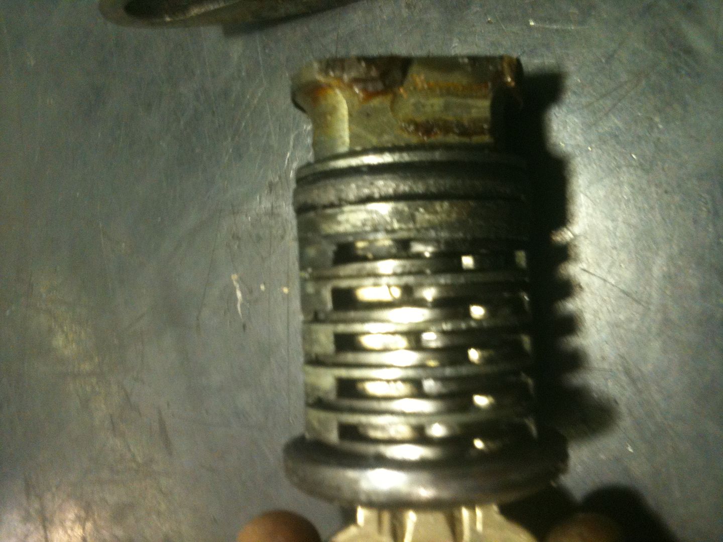
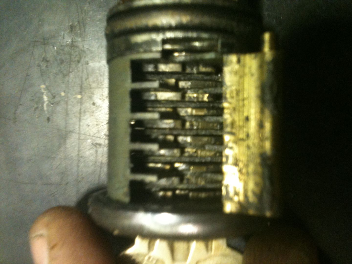
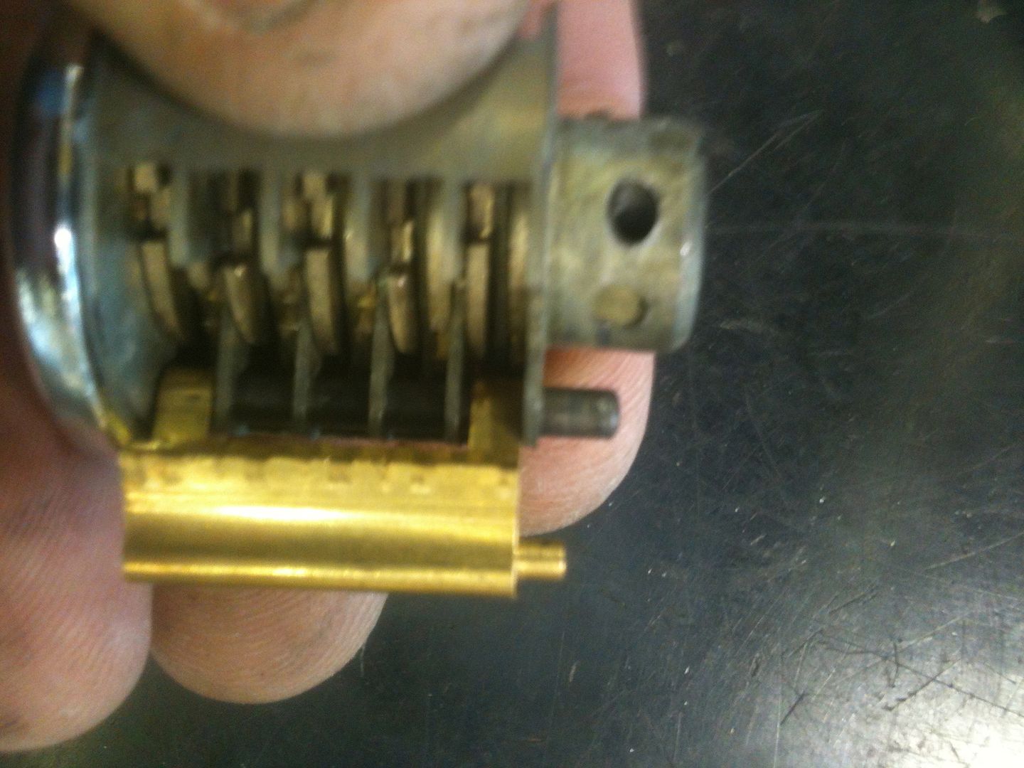
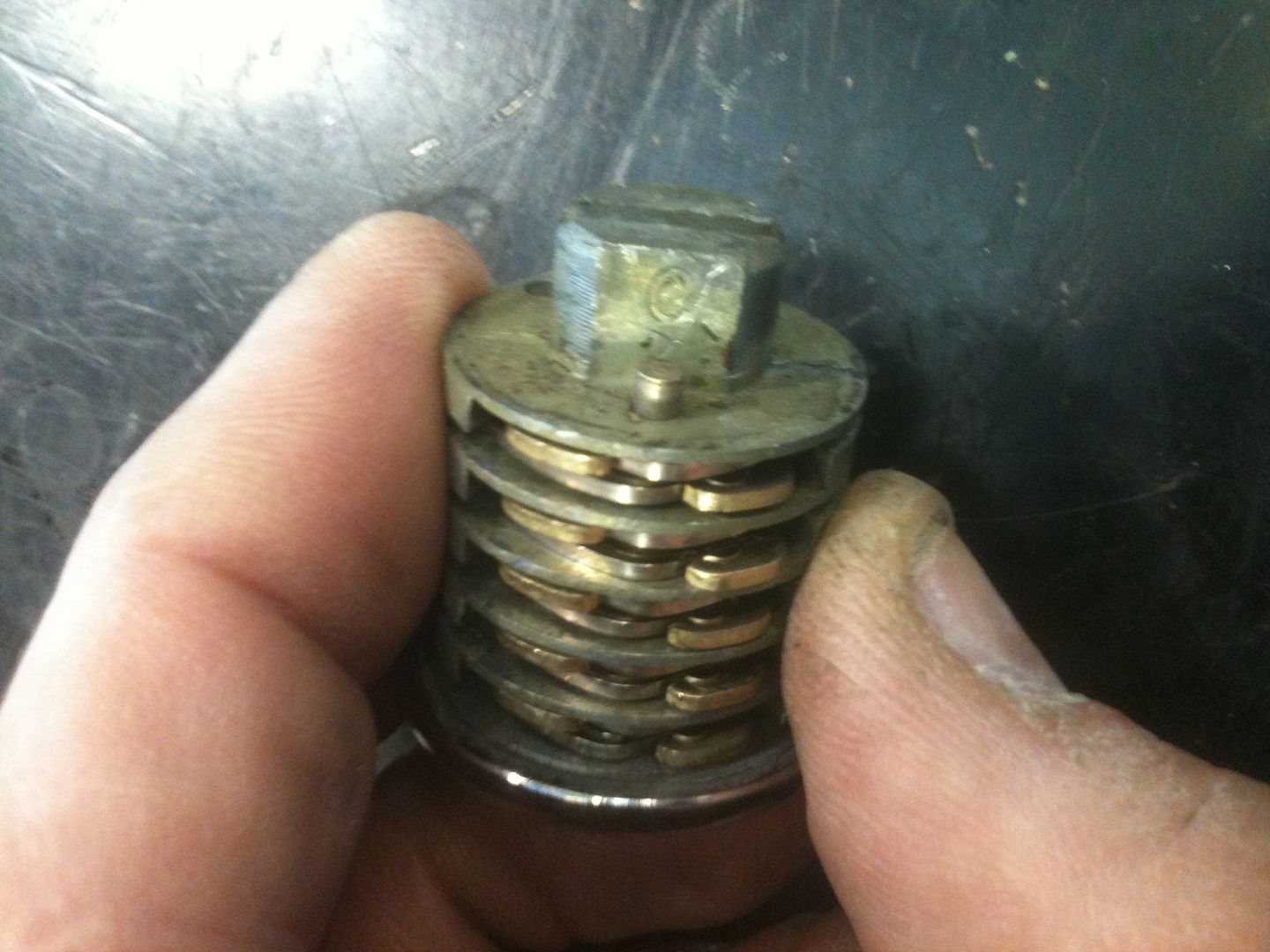
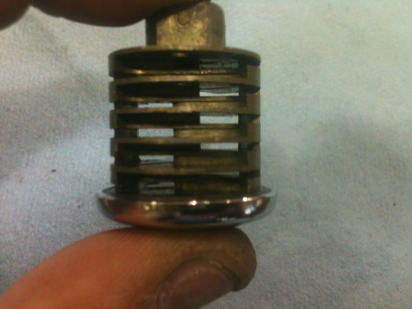
The cylinder turned 90 degrees from the above picture. You can see the levers installed, two per slot. One of each pair is facing each side of the key, and all levers pivot off the same pivot bar.
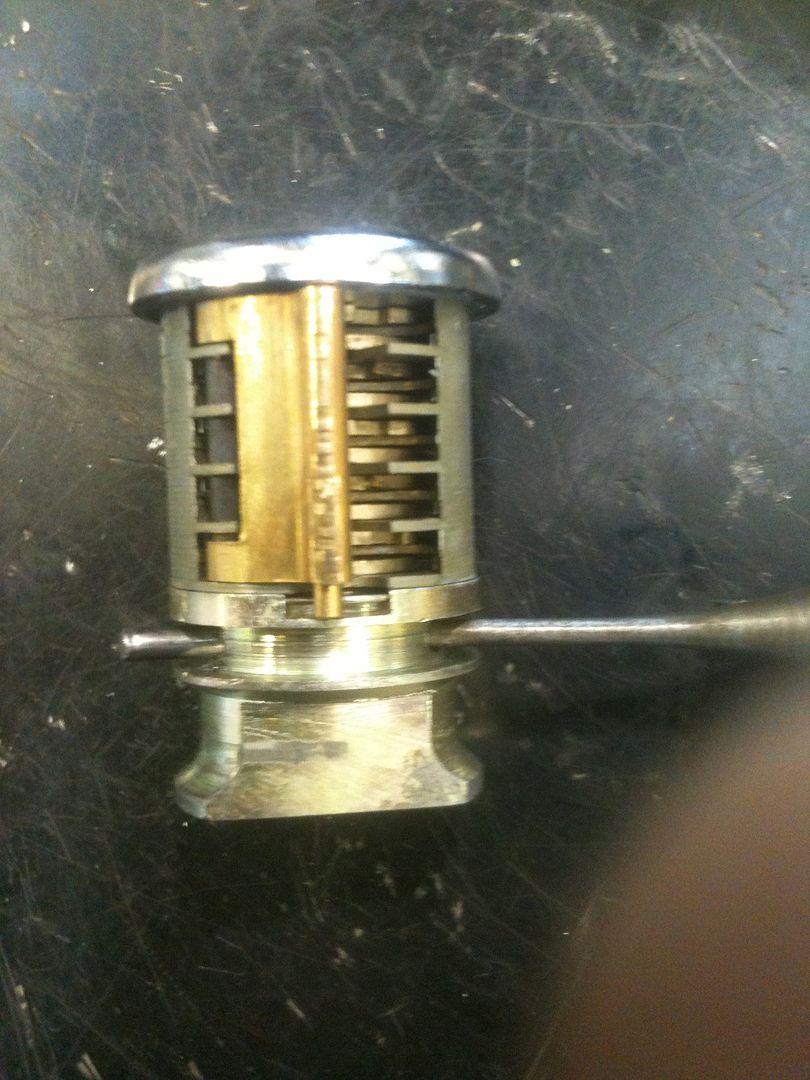
Turned 180 degrees so you can see the sidebar. The sidebar is very beefy. You are not likely to force this sidebar to turn!
The sidebar lifted up.
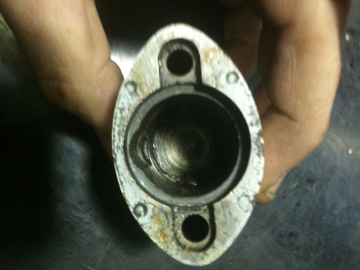
Inside the lock body. To the left, you can see the groove where the sidebar is located when in the locked position.
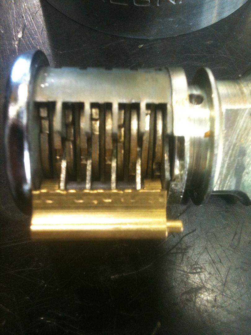
Here is what the parts look like when they are clean. You can see the gates in the levers that must line up for the sidebar.
Here the key is inserted, and the gates are lined up. They are not perfectly lined up, as the key is a little worn, but they line up enough to work for now.
The sidebar pressed down into the gates.
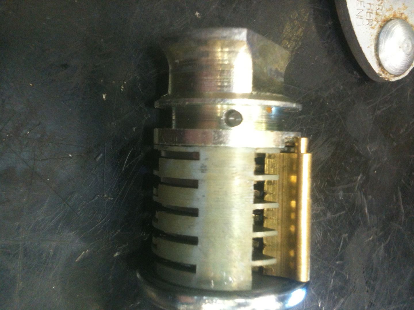
The cleaned cylinder with the o-ring removed. You can see the hole with a pin inserted inside that would be hidden by the o-ring. This pin must be removed for further disassembly.
OK, Oldfast, time to make some gut shots.
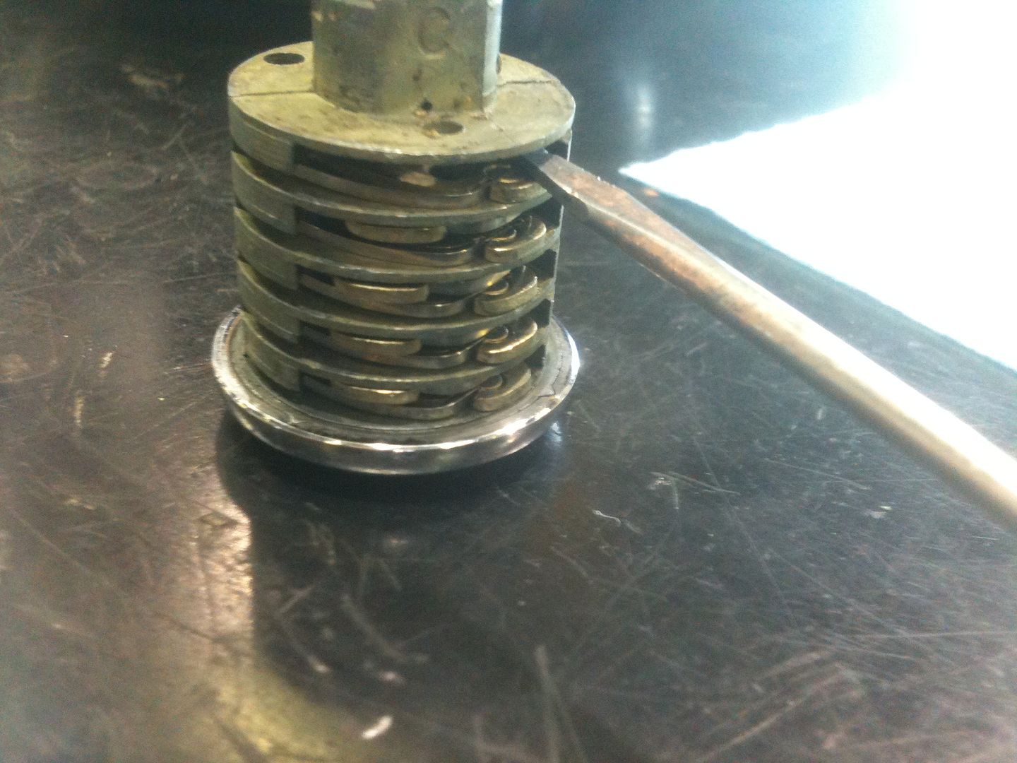
Use a drift punch to drive out the pin.
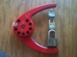
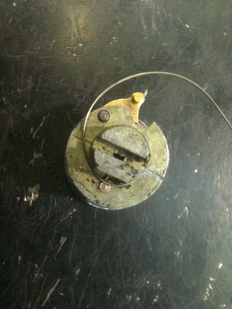
Now the cam is removed and you can see the spring that acts on the sidebar.
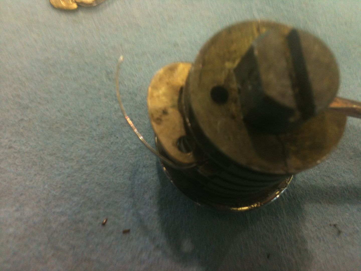
Carefully remove the spring from the plug. You can see at the bottom the spring is bent to fit into a small hole. Just pull this part straight out.
Now pull out the pivot pin for the sidebar and remove the sidebar.
As previously stated, it is a serious sidebar. And the pivot pin ain't exactly wimpy.
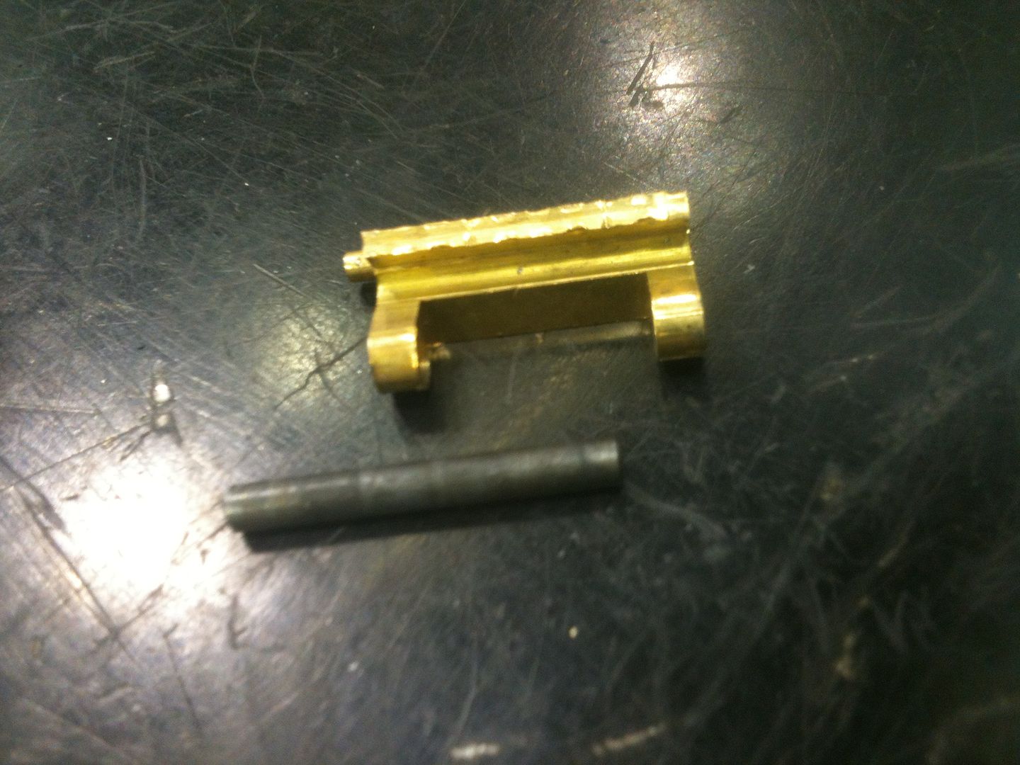
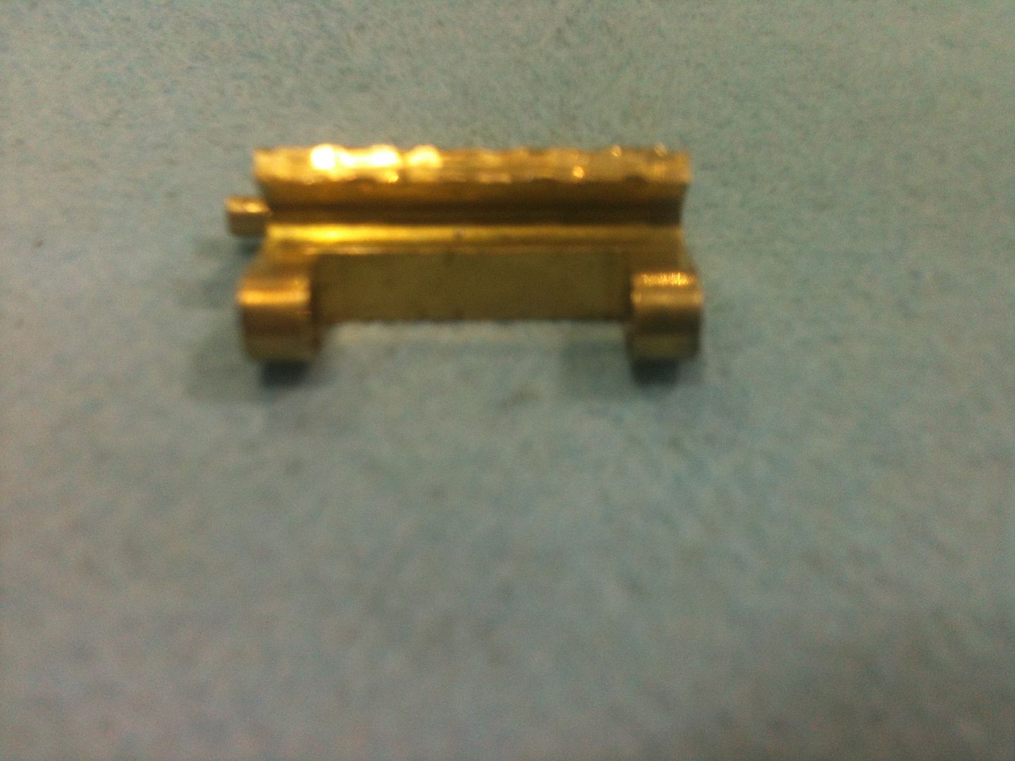
The end view of the sidebar
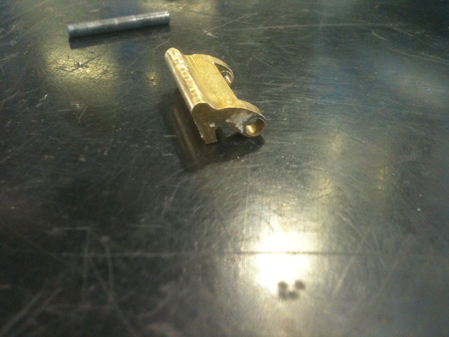
Side view of the sidebar. That post at the left side is what the wire spring presses agains to push the sidebar outwards.
Now turn the lock over and lift out the pivot pin for the levers. It will slide out easily.
Slide the lever through and out where the sidebar was installed. Push on the side without the spring, and expect to need to rotate the lever out so as to not damage the spring.
Then I figured out it is easier to push it out through the side where the lever pivot pin is located! Learn as we go, kids! As the lever is coming out:
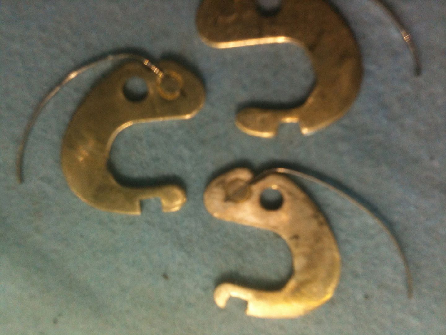
Here are the 10 levers in order. Tip of the key on the top left side, alternating sides for the first side, then top right side so they would all fit in the same picture.
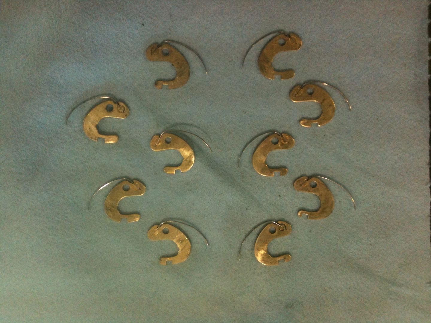
You can see the gates in this picture. Notice how the distance from the end of the arm of the lever to the gate varies. That is how the lever number is determined.
The empty cylinder ( lever pivot side)
The empty cylinder ( sidebar side)
Side view of the cylinder.
Note: On reassembly, that thin wire spring that works on the sidebar is placed, then the cam needs to be spun in the same direction as the spring as the cam in installed to 'wind in' the spring. Then the pin can be installed.
Hope you were not too bored!
Gordon
The Ingersoll locks are pretty cool lever locks with a sidebar. Have not yet succeeded in picking this lock with the rubber o-ring (bushing) installed.
For more information on the key for this lock, see 10Ringo10's topic
Here is the lock with the key:
And the keyway
Even though the lock body looks solid, it is a laminated lock, making it very strong. You can see the laminations in the area milled for the shackle area.
Now for the teardown. First, insert the key and turn it like so:
On my lock, the shackle comes out at this point. As has been told to me, the shackle should not come out, so something must be missing that fits through the hole at the bottom of the shackle.
Inside the shackle holes, you can see the Phillips screws. These are very large screws. You need a P3 size screwdriver.
Remove the key, then the screws, and cover plate.
Put the key back into the cylinder and turn it to the unlocked position.
The plug can now be removed by pulling the key. As you can see, this particular lock has plenty of dirt, and will now get a thorough cleaning before reassembly. On the left side, you can see the sidebar. Near the top you can see the very fat o-ring (they call it a bushing) that is used to dampen felt feedback when picking. Rather effectively, in my opinion.
The cylinder turned 90 degrees from the above picture. You can see the levers installed, two per slot. One of each pair is facing each side of the key, and all levers pivot off the same pivot bar.
Turned 180 degrees so you can see the sidebar. The sidebar is very beefy. You are not likely to force this sidebar to turn!
The sidebar lifted up.
Inside the lock body. To the left, you can see the groove where the sidebar is located when in the locked position.
Here is what the parts look like when they are clean. You can see the gates in the levers that must line up for the sidebar.
Here the key is inserted, and the gates are lined up. They are not perfectly lined up, as the key is a little worn, but they line up enough to work for now.
The sidebar pressed down into the gates.
The cleaned cylinder with the o-ring removed. You can see the hole with a pin inserted inside that would be hidden by the o-ring. This pin must be removed for further disassembly.
OK, Oldfast, time to make some gut shots.
Use a drift punch to drive out the pin.
Now the cam is removed and you can see the spring that acts on the sidebar.
Carefully remove the spring from the plug. You can see at the bottom the spring is bent to fit into a small hole. Just pull this part straight out.
Now pull out the pivot pin for the sidebar and remove the sidebar.
As previously stated, it is a serious sidebar. And the pivot pin ain't exactly wimpy.
The end view of the sidebar
Side view of the sidebar. That post at the left side is what the wire spring presses agains to push the sidebar outwards.
Now turn the lock over and lift out the pivot pin for the levers. It will slide out easily.
Slide the lever through and out where the sidebar was installed. Push on the side without the spring, and expect to need to rotate the lever out so as to not damage the spring.
Then I figured out it is easier to push it out through the side where the lever pivot pin is located! Learn as we go, kids! As the lever is coming out:
Here are the 10 levers in order. Tip of the key on the top left side, alternating sides for the first side, then top right side so they would all fit in the same picture.
You can see the gates in this picture. Notice how the distance from the end of the arm of the lever to the gate varies. That is how the lever number is determined.
The empty cylinder ( lever pivot side)
The empty cylinder ( sidebar side)
Side view of the cylinder.
Note: On reassembly, that thin wire spring that works on the sidebar is placed, then the cam needs to be spun in the same direction as the spring as the cam in installed to 'wind in' the spring. Then the pin can be installed.
Hope you were not too bored!
Gordon
Just when you think you've learned it all, that is when you find you haven't learned anything yet.

 Top class thanks again for all your help and work